блог

Дом

блог

  • From Purchase Order to FAT: How to Specify and Procure the Right GEKO Valve
    From Purchase Order to FAT: How to Specify and Procure the Right GEKO Valve
    Jul 07, 2026
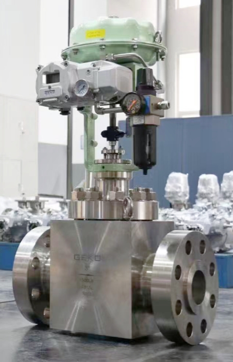
    Valve Purchase Orders: What Must Be Specified   Valve quality—whether it meets the technical, material, and documentation requirements for its intended service—is fundamentally determined at the purchase order stage. A PO that specifies only type, size, pressure class, and material grade is incomplete: it leaves critical decisions about material certification levels, inspection scope, test standards, and documentation requirements to the supplier's discretion, and the supplier will naturally default to the minimum standards that can be considered compliant.     A complete industrial valve purchase order for GEKO valves should at minimum specify the following. The applicable design standard (ASME B16.34, API 6D, API 602, or BS EN 12516) defines structural design requirements. Material specifications must include not only the alloy grade but also the ASTM or EN material standard, product form (casting, forging, bar stock), and heat treatment condition—ASTM A105 carbon steel forgings and ASTM A216 WCB carbon steel castings have different microstructures and properties; specifying one while the supplier provides the other without documenting the change is a quality oversight.   Material certification requirements define the documentation that must accompany each valve's pressure-containing parts. The minimum requirement for process plant GEKO valves is typically EN 10204 Type 3.1 material certification—a test report issued by the material manufacturer confirming the chemical composition and mechanical properties of the specific heat or lot used, with traceability to the specific heat or lot number. Type 3.2 certification (the highest level, requiring third-party verification) is applicable for nuclear service, ultra-high pressure, or other critical GEKO valve applications where additional confidence in material data is required.   Test Standards   API 598, EN 12266, or project-specific test procedures—specify the pressure, duration, test medium, and maximum allowable leakage for shell tests and seat tests. The inspection plan—defining hold points (buyer must be present for work to continue) and witness points (buyer is notified but work may continue if absent)—is included in the purchase order to ensure that the supplier prepares an Inspection and Test Plan (ITP) before manufacturing begins.     Inspection and Test Plan Development   The Inspection and Test Plan (ITP) is the quality roadmap for a GEKO valve order. It lists every significant manufacturing operation, the applicable quality standard or procedure, inspection method (visual, dimensional, NDT, pressure testing), acceptance criteria, and inspection status (hold point, witness point, or review/verify by buyer).   A typical ITP for a critical GEKO gate valve order will set hold or witness points at: material receiving and certification review (confirming correct material is procured before machining begins); casting or forging dimensional inspection (confirming castings or forgings meet dimensional tolerances before machining removes material that could mask defects); non-destructive testing (radiography or ultrasonic testing of castings, penetrant or magnetic particle testing of welds and forgings); hydrostatic shell testing; seat leakage testing; final dimensional inspection against the valve data sheet; and nameplate and marking verification. The ITP is submitted by the manufacturer and reviewed and approved by the buyer or the buyer's third-party inspector before manufacturing commences—any disagreements on scope or inspection level are resolved at this stage, not after GEKO valves have been manufactured without the required inspections.   Material Traceability   Material traceability—the ability to trace every pressure-containing part of a GEKO valve back to its original mill certificate through unique identification markings—is a fundamental quality requirement for industrial valves. Without traceability, there is no confirmation that the materials installed in the valve match those specified on the purchase order, nor can valves using a heat of material later found to have quality issues be identified.   GEKO valve pressure-containing parts must be marked with heat or melt numbers that correspond to the material certificates. For castings, this is typically stamped or cast on the body. For small machined components (stems, seat rings, nuts, and bolts), colour coding, batch bagging, or hard stamp marking is used. The manufacturer's traceability records—linking each finished component's part number and serial number to its heat number and corresponding mill certificate—form part of the GEKO valve documentation package.     Positive Material Identification (PMI) testing—using portable X-ray fluorescence (XRF) analysers—is increasingly specified on critical GEKO valve orders, particularly where the risk of material substitution (deliberate or accidental use of the wrong alloy grade) has significant safety consequences. PMI testing of finished GEKO valve components independently confirms alloy composition meets specifications, rather than relying solely on traceability documentation. This is standard practice for GEKO alloy valves in sour service (where carbon steel substituted for stainless steel could lead to catastrophic failure), nuclear, and offshore applications.   Non-Destructive Testing During Manufacturing   Non-destructive testing (NDT) is performed on GEKO valve components during manufacturing to detect internal and surface defects that could compromise the finished valve's pressure integrity or mechanical performance.   Radiographic testing (RT) of castings uses X-rays or gamma rays to image the internal structure of castings, revealing porosity, shrinkage, inclusions, and cold shuts. Acceptance criteria for radiographic testing of GEKO valve castings are defined in ASTM E446 (steel castings) and the applicable valve standards. Radiographic testing requires that the valve body thickness be within the penetration capability of the radiation source—very thick-wall, large-bore, high-pressure GEKO castings may require computed tomography (CT scanning) or ultrasonic testing as alternatives to conventional radiography where wall thickness exceeds the practical penetration limit of gamma ray sources.   Ultrasonic testing (UT) of forged bodies and castings uses high-frequency sound waves reflected from internal discontinuities in the material to detect internal defects. UT is particularly valuable for detecting planar defects (laminations, cracks) that radiography cannot reliably find because their orientation is parallel to the beam. UT requires skilled operators and properly calibrated reference blocks for meaningful sensitivity.   Liquid penetrant testing (PT) detects surface-open defects in non-ferromagnetic materials—austenitic stainless steel, aluminium, titanium, and nickel-alloy GEKO valves. A penetrant dye is applied to the surface and drawn into surface cracks by capillary action. After surface penetrant is removed, a developer draws the penetrant out of the cracks, making them visible as coloured or fluorescent indications. PT is routinely applied to body welds (body-to-bonnet welds, repair welds, nozzle welds) and machined surfaces of GEKO valves where surface cracks from machining or grinding could affect performance.   Magnetic particle testing (MT) is the ferromagnetic material (carbon steel and low-alloy steel) equivalent of PT. It uses magnetic fields and ferromagnetic particles to reveal surface and near-surface defects. For carbon steel welds on GEKO valves, MT is often preferred over PT because it is faster and can reveal near-surface defects (just below the surface) that PT cannot detect.   Dimensional Inspection   Dimensional inspection confirms that the manufactured GEKO valve meets the applicable standard and valve data sheet dimensional requirements. Critical dimensions include face-to-face or end-to-end length (per ASME B16.10 or EN 558), flange bolt circle and bolt hole dimensions (per ASME B16.5 or EN 1092-1), pressure-containing wall thickness (not less than the minimum specified in ASME B16.34 or the applicable standard), bore diameter, and seat bore diameter and geometry.   For GEKO control valves, trim dimensional inspection is particularly critical. Plug stroke dimensions—the distance the plug travels from fully closed to fully open—must match the specification as this directly determines the inherent flow characteristic (linear, equal percentage, or quick-opening). Guide clearances between the plug stem and sleeve guide must be within manufacturer tolerances to prevent sticking or excessive lateral play. Any deviation from specified trim dimensions on a GEKO valve should be investigated and the valve modified or rejected before shipment.   Factory Acceptance Testing (FAT)   Factory Acceptance Testing (FAT) is the final integrated test of the complete GEKO valve assembly—typically including the valve with its actuator, positioner, and accessories as a single unit—before shipment from the manufacturer's facility. For large, complex actuated GEKO valves (ESD valves, large-bore control valves, subsea valves), FAT is a critical event that confirms the complete assembly performs to specification before it is shipped to the field.   GEKO control valve FAT typically includes: actuator stroke testing (confirming full-open to full-close stroke and travel time); positioner calibration verification (4mA = 0% open, 20mA = 100% open, confirmed at multiple intermediate points); HART communication check (confirming positioner device parameters and diagnostic data access); pressure testing of the complete assembly including actuator supply ports; and any project-specific functional tests—split-range calibration, limit switch setting, solenoid valve functional testing for ESD applications. The buyer's inspector (or appointed third-party inspection company) should witness the FAT and sign the FAT report. The FAT report becomes part of the GEKO valve documentation package and provides the as-shipped baseline for the valve—calibration settings, stroke range, and performance parameters that maintenance engineers will refer to throughout the valve's service life.   Valve Documentation Package   The valve documentation package—sometimes referred to as the material dossier, technical file, or data book—is the permanent quality record for the GEKO valve. It should be specified in the purchase order and delivered with the valve.   A complete documentation package for a critical GEKO industrial valve includes: 1) the purchase order and technical specification; 2) the manufacturer's data sheet with actual dimensions and specifications; 3) material test certificates for all pressure-containing parts; 4) NDT reports with defect mapping and acceptance signatures; 5) hydrostatic test certificates with actual test pressures and durations; 6) the FAT report (for actuated valves); 7) any welding procedure specifications and welder qualifications (for welded GEKO valves); and 8) the manufacturer's quality dossier index confirming that all required documents are included.   These documents should be stored in the plant's document management system and linked to the GEKO valve's tag number in the CMMS. When the valve is overhauled 10 years later, the maintenance engineer can retrieve the original material certifications, trim specifications, and test records to guide repairs and confirm that any replacement parts meet the original specifications. Without these documents, every maintenance intervention starts from scratch, and the risk of incorrect parts or inadequate repairs is significantly higher.     Conclusion   Effective valve procurement and in-process inspection for GEKO valves is an investment in long-term asset reliability. For critical GEKO valve orders, the cost of third-party inspection witnessing hydrostatic testing and FAT is typically 1–3% of the valve purchase price—a fraction of the cost of finding a defect after the valve is installed in a live system. Engineers who write complete purchase orders, specify meaningful inspection hold points, and ensure that a complete documentation package is delivered with every critical GEKO valve are laying the quality foundation for preventing unexpected failures throughout the valve's service life.
    ЧИТАТЬ ДАЛЕЕ
  • GEKO Valves: Redefining High-Performance Regulation of Triple-Offset Butterfly Valves with Nine Core Technologies
    GEKO Valves: Redefining High-Performance Regulation of Triple-Offset Butterfly Valves with Nine Core Technologies
    Jul 01, 2026
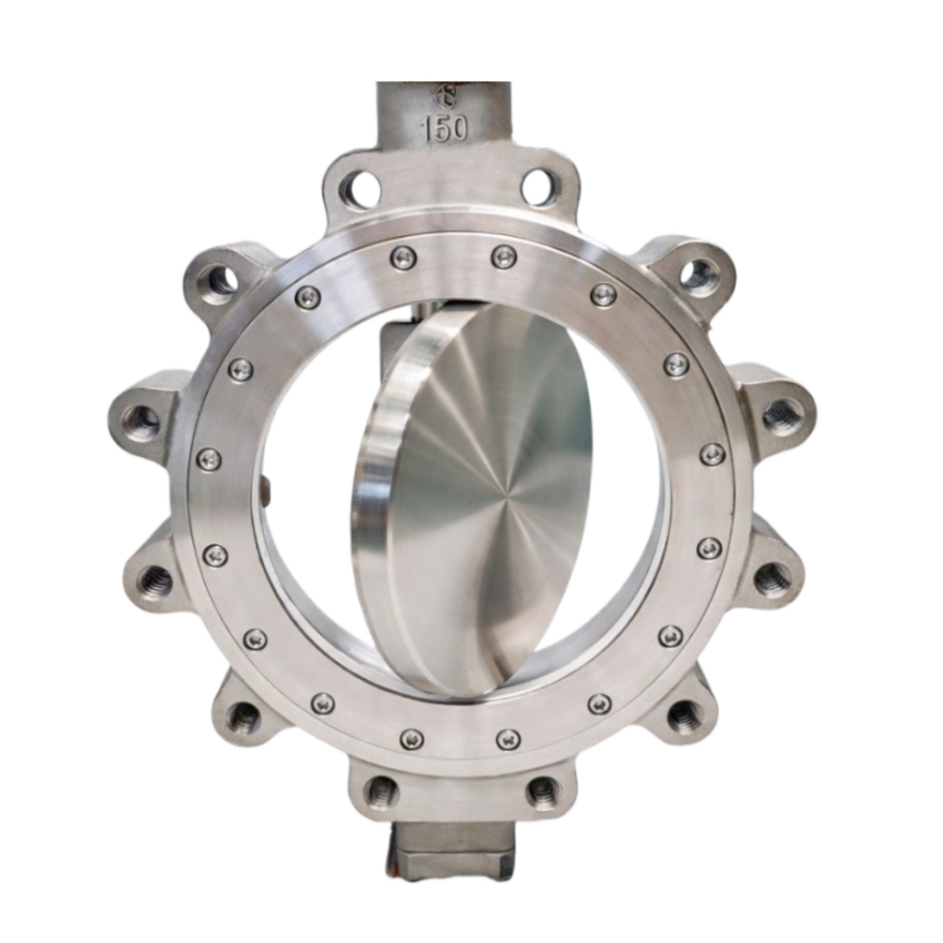
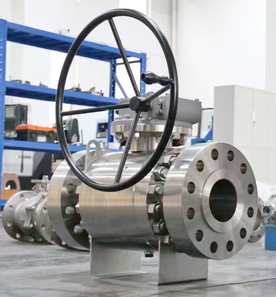
    In demanding industrial control applications, achieving "high-performance regulation" with triple-offset butterfly valves requires simultaneously overcoming three major challenges: small-opening turbulence, high-differential-pressure stability, and long-term dynamic rigidity. GEKO Fluid Control GmbH, drawing on deep expertise in fluid dynamics and precision manufacturing, has elevated the triple-offset butterfly valve from a reliable shut-off device to a precision control instrument through nine key technological innovations.   Fluid Optimization – Suppressing Disturbances at the Source Streamlined large-spherical-profile disc design optimizes the pressure distribution on the upstream face, effectively reducing vortex fluctuations at small openings.   Optimized cone half-angle and pivot radius minimize friction dead zones and enable rapid sealing-face disengagement, enhancing response sensitivity at micro-openings.   Flow Path Innovation – Balancing Pressure Reduction and Linear Control   Outlet half-orifice plate design reduces downstream vortices and lowers pressure drop, significantly improving regulation stability under high differential pressure.   Valve seat flow-guide groove design converts the inherent quick-opening characteristic into a smooth equal-percentage flow characteristic, eliminating flow surges and ensuring uniform regulation gain across the full travel range.   Severe-Service Engineering – Specialized for High Differential Pressure and Low Flow   Flow-to-open direction as standard (for blow-down, FO, and similar applications) minimizes dynamic torque fluctuations and enhances stem stability.   40–60% variable cavity reduction design in the valve seat increases flow velocity at small openings, overcoming the traditional limitation of poor controllability at low openings.   Reliability Assurance – From Torque Matching to Structural Integrity   Precise dynamic torque matching with actuator output at every opening degree ensures reliable driving force across the entire stroke.   Full-key, non-pin stem-to-disc connection provides greater load-bearing area and shear strength, ensuring rigidity and fatigue resistance under high-frequency modulation.   Anti-loosening design for sealing-face compression screws withstands high-velocity fluid impact, guaranteeing consistent sealing preload during long-term dynamic regulation.   Conclusion Through the synergistic integration of these nine precision-engineered features, GEKO has fundamentally broken the traditional perception that triple-offset butterfly valves are "only for shut-off." At GEKO, high-performance regulation represents the optimal convergence of fluid dynamics, materials science, and engineering excellence.  
    ЧИТАТЬ ДАЛЕЕ
  • GEKO Valves — Providing Precise and Reliable Control Solutions for Turbine Safety
    GEKO Valves — Providing Precise and Reliable Control Solutions for Turbine Safety
    Jun 10, 2026
    In steam turbine operation systems, VV valves, BDV valves, and RFV valves are all auxiliary protection and start-up control valves. Their names are similar, and their functions are highly related. Field operators are prone to conceptual confusion, functional misjudgment, and operational errors. This article systematically clarifies the core definitions, structural principles, interlock logic, operational requirements, and key differences of these three types of valves, based on turbine design principles, unit start-stop logic, and field operation standards, providing professional technical reference for operation, maintenance, commissioning, and overhaul. GEKO Valves, with their high-precision pneumatic control technology and rigorous industrial validation, have become a trusted brand in the manufacturing and system integration of these critical valves.     I. Core Valve Definitions & Structural Working Principles (i) VV Valve (Vent Valve — HP Exhaust Vent Valve) Located on the high-pressure (HP) exhaust pipeline, this special vent and pressure relief valve leads directly to the condenser and drain flash tank. It is mainly used in intermediate-pressure (IP) start-up units to solve windage overheating issues in the HP cylinder under low load or no-inlet steam conditions, while also providing rapid pressure relief after tripping to prevent overspeed.     During IP start-up or low-load operation, the HP cylinder has little or no inlet steam, and the HP exhaust non-return valve remains closed. The blades inside the HP cylinder generate significant heat due to air friction (windage), which can easily cause overheating damage to the HP blades and casing. After a turbine trip, residual steam in the HP cylinder can leak into the vacuum state of the IP cylinder through HP-IP shaft seals, creating a risk of rotor overspeed. The VV valve quickly evacuates residual steam from the HP cylinder to avoid these risks.   It uses a pneumatically controlled, air-to-close design, consisting of an air supply, cylinder, spring assembly, and solenoid valve. GEKO Valves features an optimized high-temperature spring assembly and low-friction cylinder in this product, ensuring reliable valve opening under air failure conditions, with solenoid valve response time ≤0.5 seconds, significantly improving the timeliness of windage overheating protection.     (ii) BDV Valve (Break Drain Valve — Turbine Emergency Drain Valve) An emergency pressure relief protection valve specifically designed for combined HP-IP turbines, also known as the HP-IP shaft seal residual steam dump valve. Its core function is to quickly discharge steam that leaks past shaft seals under unit load rejection or trip conditions, eliminating the risk of turbine overspeed.     During load rejection or emergency trip of combined HP-IP units, residual steam in the HP cylinder and HP inlet pipes can leak through the HP-IP shaft seal gaps into the IP and low-pressure (LP) cylinders, creating additional driving force on the rotor. If seal teeth are worn or gaps increase, the amount of leaking steam increases, significantly raising the risk of overspeed. The BDV valve directs this residual shaft seal steam directly into the condenser, quickly releasing pressure and completely blocking the overspeed path.   It uses an electromagnetic-pneumatic linkage structure, controlled by the stroke signal of the IP control valve oil servo. GEKO Valves' BDV product adopts a redundant dual-solenoid valve design with a highly reliable pneumatic control circuit, achieving full-stroke action within 0.3 seconds after the oil servo stroke signal is triggered, effectively preventing the escalation of overspeed accidents.   (iii) RFV Valve (Reheat Warm-up Valve — HP Cylinder Reverse Warming Valve) A dedicated warm-up control valve for cold starts, used to pre-heat the HP cylinder before cold start, eliminating casing temperature differences, reducing thermal stress, and ensuring the unit meets parameters for rolling.   During a cold start, the HP cylinder casing and internal components are at very low temperatures. Directly introducing steam for rolling would create huge thermal stress, leading to casing deformation, metal cracks, and excessive shaft vibration. The RFV valve introduces auxiliary steam upstream of the HP exhaust non-return valve. The steam flows evenly through the HP cylinder and is discharged through HP inner casing drains and HP inlet pipe drains, gradually raising the casing temperature to achieve uniform warm-up.   GEKO Valves has specifically developed an RFV valve with linear regulation characteristics for these operating conditions. It uses a low-leakage seal design and anti-seize valve core, allowing precise temperature control under low flow and low differential pressure conditions, with warming rate control accuracy of ±1.5°C/h, significantly outperforming conventional products.     II. Valve Interlock Control Logic VV Valve Interlock Logic Close Interlock: Receives stroke switch signals from the four HP control valve pre-pilot valves. When all four pre-pilot valves are fully open and unit steam flow reaches 0.5% BMCR, the VV valve automatically closes. 1 minute after unit grid connection, the HP exhaust non-return valve opens, and the VV valve closes via interlock.   Open Interlock: Automatically opens during initial IP start-up and low-load windage conditions. Immediately opens via interlock after turbine trip to quickly evacuate residual HP steam.   BDV Valve Interlock Logic Close Interlock: Controlled by IP control valve oil servo stroke. When oil servo stroke ≥30mm, or when the left/right IP control valve opening reaches 15%~16% (corresponding to ~5% flow command) and the pre-pilot valve is fully open, the BDV valve automatically closes.   Open Interlock: Automatically opens when IP control valve oil servo stroke <30mm. Quickly opens via interlock under turbine trip and load rejection conditions to discharge shaft seal steam.   Pre-Pilot Valve Function Note The turbine control valve pre-pilot valve is an auxiliary valve for the main valve disc. Before the main valve disc opens, the pre-pilot valve opens first, allowing new steam to flow through the pre-pilot passage, balancing the pressure differential across the main valve. This significantly reduces the force required to open the main valve, reduces the oil servo load, and avoids difficult or stuck valve opening.   III. Field Operation & Operational Requirements Pre-Start Check: Before unit start-up and rolling, the open/close status of VV and BDV valves must be confirmed both locally and via DCS. Never start the unit with abnormal valve status.   IP Start-Up Operation: Before start-up, confirm VV and BDV valves are open. If a manual isolation valve is installed upstream of the VV valve, check that it is fully open to avoid false action due to abnormal instrument air pressure or solenoid valve failure.   Post-Valve Transfer: After completing valve transfer following IP start-up, double-check (on DEH screen and locally) that the VV valve is fully closed to prevent steam leakage or pressure abnormalities after HP cylinder admission.   Unstable Conditions: During initial start-up, commissioning, or unstable operation, do not close the manual isolation valve upstream of the VV valve, leaving an emergency path available. After stable operation, close the manual isolation valve promptly.   Post-Trip Emergency: Immediately after a trip during operation, arrange personnel to locally check and open the manual isolation valve upstream of the VV valve, while verifying BDV valve position via DCS and locally, ensuring both valves open correctly for rapid pressure relief.   Normal Start-Stop: Monitor BDV valve position feedback in real-time after the interceptor valve opens during start-up and after a trip to ensure reliable interlock action.   Cold Start Warm-Up: Before rolling during a cold start, open the RFV valve for HP cylinder reverse warming. Monitor drain paths and casing temperature rise rate. Close the RFV valve after warm-up and proceed with normal start-up.   GEKO Valve Note: Accurate valve status feedback is critical in the above operations. GEKO valves come standard with high-precision limit switches and 4-20mA position transmitters, seamlessly integrating with DCS systems to significantly reduce misjudgment risks.     IV. Key Differences & Functions of the Three Valves     Valve Core Function Control Signal Source Main Application VV Valve HP cylinder venting, addresses windage overheating, auxiliary pressure relief after trip HP control valve pre-pilot stroke, steam flow, trip signal Initial IP start-up, low-load operation, turbine trip BDV Valve Discharges shaft seal steam, core overspeed prevention IP control valve oil servo stroke, IP valve opening signal Load rejection, emergency trip, IP valve not fully open RFV Valve HP cylinder cold pre-warming, reduces thermal stress Manual control + warm-up sequence Before turbine cold start     Key Functional Distinction:   VV Valve: Focuses on daily windage overheating protection; auxiliary pressure relief after trip.   BDV Valve: Core overspeed protection valve, specifically targeting shaft seal steam leakage.   RFV Valve: Only used for cold start warm-up, no accident protection function. These three functions are not interchangeable.   GEKO Valves has developed dedicated valve series for each of these three needs, with differentiated designs from material selection (e.g., high-temperature alloy seat for VV valve), sealing structure (metal hard seal + flexible graphite for BDV valve), to actuator configuration (smart positioner optional for RFV valve), ensuring the right valve for each application.   V. Shaft Seal & Stem Leakage System Summary (Typical Plant Configuration) Main Stop Valve: 1st stage leakage → sealing steam header, 2nd stage leakage → sealing steam return header   HP Control Valve: 1st stage leakage → reheater, 2nd stage leakage → sealing steam header   IP Interceptor Valve: Only 1st stage leakage → sealing steam header   BDV Valve: 1st stage leakage → reheater, 2nd stage leakage → sealing steam header   VV Valve: 1st stage leakage → 4th extraction pipe, 2nd stage leakage → sealing steam header   HP Shaft Seal: 3rd stage leakage → 4th extraction pipe   In the above system, GEKO Valves provides matching shaft seal leak control valves and stop valves, ensuring stable leak-off pressures, reducing steam waste, and improving unit thermal economy.   VI. Core Technical Q&A 1. What are the core functions of the VV valve and BDV valve? VV Valve: During IP start-up and low-load operation, connects the HP cylinder to condenser vacuum, evacuating air from the cylinder to reduce windage heating and avoid HP blade/casing overheating. After a trip, quickly releases residual HP steam, assisting in overspeed prevention.   BDV Valve: During a trip or load rejection, quickly discharges steam that leaks from the high-pressure side through shaft seal gaps into the IP cylinder, directly cutting off additional driving force. It is a critical overspeed prevention valve.   2. Why choose GEKO valves for these critical applications? GEKO Valves has over 20 years of experience in developing specialized valves for steam turbines. Our products hold ISO 15848-1 fugitive emission certification and SIL2 functional safety certification. The VV, BDV, and RFV series have accumulated over 100,000 hours of safe operation in multiple ultra-supercritical and subcritical units worldwide, with an action success rate exceeding 99.96%. GEKO provides full-cycle technical support — from valve selection and interlock logic optimization to field commissioning — helping power plants reduce unplanned outage risks caused by valve misoperation or failure to operate.     Conclusion VV, BDV, and RFV valves each play a distinct, non-interchangeable role in turbine start-up and protection. Operating and maintenance personnel must not only master their working principles and interlock logic but also pay attention to the quality and reliability of the valves themselves. GEKO Valves, with solid technical expertise and extensive field experience, provides high-performance, high-reliability products and complete solutions for these three valve types, helping power plants achieve safer and more efficient operation.   For specific valve selection and interlock settings, please refer to the OEM design drawings and actual site conditions. GEKO Valves offers tailored technical consultation.
    ЧИТАТЬ ДАЛЕЕ

  • Geko Fluid Control Technology (Changzhou) Wins Valve Supply Bid from CSSC No.703 Research Institute
    Geko Fluid Control Technology (Changzhou) Wins Valve Supply Bid from CSSC No.703 Research Institute
    Jun 08, 2026
    Geko Fluid Control Technology (Changzhou) Co., Ltd. has successfully won a competitive bidding project from the No.703 Research Institute of China State Shipbuilding Corporation Limited (CSSC). The bid award was officially announced on May 7, 2026, under project number TPJG202605070010.     The scope of supply includes ball valves, butterfly valves, globe valves, and check valves – marking an important milestone for Geko in the marine and ocean engineering sector.   German Engineering, Deep Roots in China   Geko Fluid Control Technology (Changzhou) is the core Chinese subsidiary of GEKO, a well-known European control valve manufacturer with over 60 years of history. GEKO is recognized for high-pressure and extreme-temperature resistance, with some products rated up to 60,000 psi and temperature ranges from -252°C to 649°C.     Founded in 2008 with a registered capital of 50.1 million RMB, the Chinese company is headquartered in Changzhou, Jiangsu Province. Its new factory, launched in 2022, has an annual production capacity of 120,000 units, manufacturing pneumatic/electric ball valves, butterfly valves, control valves, gate valves, globe valves, check valves, actuators, positioners, and limit switches.   Proven Track Record: National Flagship Projects     With robust product quality, Geko has participated in multiple prestigious national projects:   High-speed rail: Custom valves for CRRC high-speed train sets, passing 300,000 km road tests. Ultra-high voltage (UHV) grids: Electric explosion-proof ball valves with a 40-year design life for State Grid. Aerospace & nuclear power: Supply to rocket launch bases, Pakistan nuclear power projects, and multiple Belt and Road international projects. Domestic nuclear power: Products applied in major nuclear projects including the “Linglong One” small modular reactor. Strategic Focus: Hydrogen & New Energy   GEKO’s global strategic priority is the hydrogen energy sector, covering the entire value chain of production, storage, transport, and refueling. Core technologies include anti-hydrogen embrittlement materials, low fugitive emissions, fire and electrostatic discharge protection, and high-pressure (including liquid hydrogen) handling. Applications span hydrogen metallurgy, hydrogen power generation, hydrogen refueling stations, and fuel cell vessels/vehicles.   Leadership Perspective: Hugo Huang   Hugo Huang (Huang Wanzheng), General Manager of Geko Fluid Control Technology (Changzhou), has led GEKO’s China market expansion since 2005. He commented: *"Winning the CSSC No.703 Research Institute project is further recognition of our technical strength and delivery capability. We will continue deepening our presence in marine, nuclear, hydrogen, UHV, aerospace, and other high-end industrial valve markets, contributing to the localization of critical equipment for national strategic projects."*
    ЧИТАТЬ ДАЛЕЕ
  • Geko Valve & Control Makes Early Moves in Pumped Storage Power Stations – A Promising Five Years Ahead
    Geko Valve & Control Makes Early Moves in Pumped Storage Power Stations – A Promising Five Years Ahead
    Jun 08, 2026
    As the global energy structure accelerates toward renewables, pumped storage power stations have become the most mature and economically viable large-scale energy storage solution. In response, Geko Valve & Control, a German manufacturer of industrial valves and control systems, has made early moves in the pumped storage power station sector – with a strong focus on electric ball valves for hydropower plants.     Founded in 1956 (with roots tracing back to 1946), Geko entered the Chinese market in 2005 and established a production base and sales center in Changzhou. The company has already demonstrated its reliability in critical hydropower applications, supplying valves for China's national flagship project – the Baihetan Hydropower Plant.   Tailored Solution for Pumped Storage: GKQ0350-GKV225 DN150 PN25     For pumped storage applications requiring frequent start-stop cycles, high differential pressure, bidirectional flow, and ultra-low fugitive emissions, Geko introduces the GKQ0350-GKV225 electric ball valve – featuring DN150 nominal diameter and PN25 pressure rating. This model is specifically engineered to meet the stringent demands of pumped storage power stations.   Key technologies include HVOF spraying (rocket spray process, hardness up to HRC 66–72) for superior erosion and corrosion resistance, backed by TÜV ISO15848 low-leakage certification and ISO 10497 fire safety compliance.   Looking Ahead   Geko expects strong growth over the next five years as China's 14th Five-Year Plan and subsequent initiatives roll out dozens of new pumped storage projects. The company will continue to advance its valve and control technologies for pumped storage power station systems, contributing to the next-generation power grid.   Beyond hydropower, Geko also serves high-precision and demanding industries including hydrogen energy, LNG, green methanol, nuclear power (e.g., the "Linglong One" mini-reactor), semiconductors, aerospace, and biopharmaceuticals – reinforcing its position as a forward-looking industrial valve specialist.
    ЧИТАТЬ ДАЛЕЕ
  • From 550°C to 1100°C: How to Choose High-Temperature Valve Materials? – A Technical Insight from GEKO Valves
    Jun 03, 2026
    In high-temperature service conditions, the maximum allowable operating temperature of valve materials is one of the key parameters determining operational safety, stability, and service life. Due to differences in composition and microstructure, different materials have significantly different temperature limits. As a professional manufacturer of high-temperature valves, GEKO Valves, drawing on years of engineering experience, provides a systematic analysis of the three most widely used high-temperature valve material families – chrome-molybdenum steel, stainless steel, and nickel-based alloys – to help users make scientific selections based on actual operating conditions and avoid safety hazards such as seal failure and structural deformation caused by exceeding temperature limits.     Chrome-Molybdenum Steel – The Mainstream Choice for Medium-to-High Temperatures   By adding chromium and molybdenum to carbon steel, chrome-molybdenum steel significantly improves creep resistance and oxidation resistance, solving the problems of graphitization and strength degradation commonly seen in ordinary carbon steel at high temperatures. The GEKO chrome-molybdenum steel valve series covers the following common grades:   15CrMoG (equivalent to ASTM A217 WC5): Long-term temperature limit of approximately 540–550°C, suitable for auxiliary steam lines in power plants. WC9: Temperature resistance up to 593°C, widely used in main steam lines of subcritical units in thermal power plants. 2.25Cr-1Mo: Conventional design temperature rating of approximately 565–590°C, and up to 650°C with special stress-relieved treatment. It can reliably serve in medium-to-high temperature environments such as hydrogenation units. GEKO Valves applies optimized heat treatment processes to this material to further enhance high-temperature stability.     Stainless Steel – Combining Corrosion Resistance and High-Temperature Performance   Austenitic stainless steels are widely used due to their good corrosion resistance and high-temperature stability. The GEKO stainless steel high-temperature valve series offers multiple grade options:   304 / 304H: Type 304 is generally recommended for long-term use not exceeding 550°C; for higher temperatures, 304H can be selected. Suitable for high-temperature fluid control without strong corrosion. 316L: Long-term temperature resistance of approximately 550–560°C, suitable for high-temperature corrosive media containing sulfur. 321: Contains titanium, offering excellent resistance to intergranular corrosion, with a long-term temperature resistance of up to 650°C, ideal for high-temperature wet steam systems. GEKO 321 series valves have been successfully applied in multiple steam pipeline projects. 310S: Due to its high chromium and nickel content, it exhibits excellent oxidation and creep resistance, with a long-term temperature resistance of up to 700°C (in oxidizing atmospheres). Commonly used in heat treatment furnaces, incinerator exhaust systems, and other high-temperature applications. GEKO 310S valves provide reliable performance in high-temperature oxidizing environments.   Nickel-Based Alloys – The Core Material for Ultra-High Temperatures   Nickel-based alloys, relying on the excellent high-temperature stability of nickel combined with strengthening effects of chromium, molybdenum, niobium, and other elements, offer significantly higher temperature limits than chrome-molybdenum steels and stainless steels. The GEKO nickel-based alloy valve series covers the following high-end grades:   Inconel 625: Long-term continuous operating temperature of approximately 650–700°C, with short-term peaks up to 815°C. Suitable for petrochemical cracking furnace outlets, high-temperature gas systems, and similar applications. Inconel 718: Long-term temperature resistance of 650–700°C, and up to 980°C for short periods (≤1 hour), combining high-temperature strength and corrosion resistance. Haynes 282 and other high-end grades: Long-term temperature resistance covering 650–950°C. Directional solidification processes further enhance creep strength, making them suitable for extreme high-temperature applications such as nuclear power and concentrated solar power. GEKO Valves can provide customized solutions in these high-end materials. Hastelloy C-276: Long-term temperature resistance recommended within 540–590°C, with strong resistance to highly corrosive acids, suitable for medium-to-high temperature acidic fluid conditions.   Additional Sizing Considerations: Beyond Body Material – GEKO's Complete High-Temperature Sealing Solution   It is important to note that the temperature limit of a high-temperature valve is not the only criterion for selection. The corrosiveness of the medium, operating pressure, and the temperature resistance of sealing materials and seating surfaces must also be considered.   Sealing material: Flexible graphite packing has a recommended long-term temperature limit of 450–500°C in air, and up to 1600°C in inert atmospheres, making it the first choice for high-temperature sealing. GEKO high-temperature valves are standardly equipped with high-quality flexible graphite packing to ensure reliable sealing under high-temperature conditions. Seating surface material: Cobalt-based alloys (such as Stellite 6) welded on sealing surfaces can withstand temperatures above 850°C, improving erosion and wear resistance. GEKO Valves offers Stellite alloy hardfacing options based on specific service requirements. GEKO Valves Recommendation: In practice, the body material, sealing material, and seating surface hardfacing should be matched according to the temperature grade of the operating condition, forming a complete high-temperature resistance system. GEKO Valves provides a complete high-temperature solution, from material selection and sealing pairing to complete valve assembly, ensuring reliable long-term operation of your equipment in the range of 550°C to 1100°C.   Contact the GEKO Valves technical team for high-temperature valve selection advice tailored to your specific operating conditions.  
    ЧИТАТЬ ДАЛЕЕ
  • What's the Difference Between O-Port and V-Port Ball Valves? – Insights from GEKO Valves
    What's the Difference Between O-Port and V-Port Ball Valves? – Insights from GEKO Valves
    Jun 02, 2026
    In industrial fluid control systems, O-port ball valves and V-port ball valves are two common types with different design focuses. Based on years of engineering experience, GEKO Valves provides a detailed comparison in terms of structural design, flow characteristics, regulating performance, shut-off capability, and more, to help you make the right choice.     1. Structural Design   O-port ball valve: The ball has a circular through-hole in the center. When fully open, the hole diameter is basically the same as the pipeline inner diameter, forming a straight flow path. GEKO O-port ball valves are precision-machined for low flow resistance and high sealing performance. V-port ball valve: The ball features a V-shaped notch. GEKO V-port ball valves allow customization of V-notch angle and size according to media characteristics, improving shearing and regulating capabilities.     2. Flow Characteristics   O-port ball valve: Approximate quick-opening characteristic. Flow increases sharply at small openings (e.g., 0°–15°), and reaches 80%–90% of full flow at around 20°–30°. Suitable for fast on/off service, poor throttling capability. V-port ball valve: Approximate equal-percentage characteristic. Flow increases smoothly and linearly with opening, designed for precise throttling. GEKO V-port ball valves maintain excellent controllability even at small openings.     3. Throttling Performance   O-port ball valve: Poor throttling performance. Flow changes drastically at small openings, making precise control difficult; prone to cavitation, vibration, and noise at medium openings. Recommended only for on/off (two-position) control. V-port ball valve: Excellent throttling performance. The V-notch provides stable, predictable flow control, and the V-shaped edge offers shearing action, making it ideal for fibrous, particulate, or slurry media. GEKO V-port ball valves deliver reliable and stable throttling performance.   4. Shut-Off Capability   O-port ball valve: Excellent shut-off capability. With soft or metal seats, it can achieve bubble-tight zero leakage. GEKO O-port ball valves are widely used in applications requiring strict shut-off. V-port ball valve: Relatively weaker shut-off capability. Theoretically, it cannot achieve the same zero-leakage performance as an O-port valve of the same size. Designed primarily for throttling, not absolute shut-off.   5. Flow Resistance   O-port ball valve: Very low flow resistance when fully open, close to a straight pipe, resulting in minimal pressure drop. GEKO O-port ball valves feature optimized flow paths for even lower energy consumption. V-port ball valve: The V-notch creates some flow resistance even when fully open, resulting in a higher pressure drop than an O-port valve.   6. Erosion & Wear Resistance (for media containing solid particles)   O-port ball valve: When switching in particulate-laden media, particles can become trapped between the ball and seat, leading to scoring, wear, or even seizure. V-port ball valve: The sharp edge of the V-notch shears fibers and solid particles, preventing clogging. Better suited for dirty media such as high-viscosity, crystallizing, particulate-laden, or slurry applications. GEKO V-port ball valves excel in wastewater, pulp, slurry, and similar tough services.   7. Typical Applications   O-port ball valve: Suitable for clean liquids and gases (e.g., water, steam, oil, natural gas). The first choice for fast and reliable shut-off. V-port ball valve: Suitable for applications requiring precise flow throttling, especially for challenging media such as pulp, wastewater, slurry, high-viscosity fluids, and crystallizing or scaling liquids. GEKO V-port ball valves are a reliable choice for control valve applications.   8. Cost   Generally, V-port ball valves are more expensive than O-port ball valves of the same size and material due to the more complex machining of the V-notch. GEKO Valves offers various configuration options to balance performance and cost – contact us for sizing recommendations.     9.How to Choose? – GEKO Valve Selection Guide     Requirement Recommended Type Reliable shut-off, zero leakage GEKO O-port ball valve Precise flow throttling GEKO V-port ball valve Clean media Either (depending on functional needs) Media containing particles, fibers, viscous or scaling substances Prioritize GEKO V-port ball valve Budget-limited and on/off only GEKO O-port ball valve   One-sentence summary: O-port ball valves are shut-off experts (tight shut-off), while V-port ball valves are throttling experts (precise control,不怕脏 – not afraid of dirty media). Your choice depends on whether you need shut-off or throttling, and the characteristics of your media.   Why Choose GEKO Valves?   German engineering standards and strict quality control Full range of O-port and V-port ball valves Customizable V-notch design for demanding applications Professional team offering free sizing and selection advice Fast delivery and comprehensive after-sales support 📞 Contact GEKO Valves today for a solution tailored to your operating conditions.  
    ЧИТАТЬ ДАЛЕЕ
  • GEKO Metal Bellows Sealed Globe Valve
    GEKO Metal Bellows Sealed Globe Valve
    May 24, 2026
    GEKO: A Dedicated Valve Brand for Highly Corrosive and Highly Toxic Chemical Media   GEKO is positioned as a specialized valve brand for chemical applications involving highly corrosive and extremely toxic media. Its core product is the metal bellows sealed globe valve, designed for zero fugitive emissions, zero external leakage, and long service life. It is an ideal valve solution for highly toxic media such as chlorine, phosgene, hydrogen fluoride, and other hazardous gases.   Compared with conventional packed globe valves, GEKO bellows sealed globe valves reduce fugitive emissions by more than 100 times and offer a service life 5 to 10 times longer. Compared with other bellows valve designs, GEKO valves feature a more compact structure, easier maintenance, and lower overall operating costs.     Product Series and Technical Parameters   Main Product Series: Bellows Sealed Globe Valves T-Type Straight-Through Globe Valve This is the standard design, covering sizes from DN15 to DN600, pressure ratings from PN16 to PN160 or Class 150 to Class 2500, and operating temperatures from -20°C to +450°C. Y-Type Globe Valve The Y-pattern design offers lower flow resistance and is suitable for high-viscosity media and fluids containing particles. Angle Type Globe Valve With a 90-degree flow path, the angle type globe valve saves installation space and is commonly used for small-diameter, high-pressure applications. Chlorine Service Valve GEKO chlorine valves are designed specifically for dry and wet chlorine service. They meet European chlorine industry standards and are among the products certified by only a limited number of qualified manufacturers. These valves provide excellent corrosion resistance and zero external leakage for chlorine applications.   Materials and Pressure Ratings Valve Body: WCB carbon steel, CF8M stainless steel 316, Alloy 20, Hastelloy C for highly corrosive applications. Bellows: Multi-layer stainless steel bellows, such as 316L or 321, with a fatigue life of no less than 10,000 opening and closing cycles. Disc and Seat: Stellite 6 hardfacing, hardness HRC40–50, providing excellent wear resistance and erosion resistance.   Core Structure and Sealing Principle    Integral Structure: Three-Piece Design, Bellows Seal, No Packing Valve Body The valve body is forged or cast in accordance with ASME B16.34 and can be supplied with flanged or butt-weld ends. Bellows Assembly The multi-layer welded stainless steel bellows is connected to the valve stem at one end and to the valve body at the other end. This structure completely isolates the process medium from the atmosphere, eliminating the need for traditional packing and preventing external leakage. Valve Stem The two-section rising stem design provides reliable sealing performance. The stem is Stellite-coated, anti-rotation, and designed for low-friction operation. Disc and Seat The conical metal-to-metal sealing structure ensures tight shut-off and zero internal leakage. During opening and closing, the sealing surfaces are self-cleaned to maintain reliable sealing performance. Bonnet Flange   The bonnet flange adopts a tongue-and-groove design with a flexible graphite gasket, providing fire-safe performance in accordance with API 607.   Patented Sealing Mechanism for Zero External Leakage Absolute Isolation by Bellows The process medium is sealed inside the bellows, achieving zero fugitive emissions in compliance with TA-Luft requirements. Since there is no packing wear, the risk of external leakage is eliminated. Elastic Preload Compensation The bellows provides inherent elasticity, allowing automatic compensation for thermal expansion, contraction, and wear. This ensures stable sealing pressure during long-term operation. Conical Hard Sealing The disc and seat are precision-lapped to a micron-level finish. When closed, the metal sealing surfaces fit tightly together, achieving zero internal leakage in accordance with API 598. Anti-Torque Design   The bellows is equipped with an anti-rotation limiting structure to prevent torsional fatigue during valve operation, significantly extending service life.     Application Conditions and Performance Limits   Recommended Applications   GEKO bellows sealed globe valves are especially suitable for the following severe service conditions: Media: dry and wet chlorine, phosgene, hydrogen fluoride, hydrogen chloride, toxic gases, high-temperature steam, hot alkali, and high-temperature media containing particles. Temperature Range: -50°C to +450°C; special alloy designs can reach up to 550°C. The valve maintains stable performance under alternating hot and cold conditions. Pressure Range: Class 150 to Class 2500, or PN16 to PN160, with reliable high-pressure sealing and no internal leakage. Industries: chlor-alkali chemical plants, coal chemical industry, petroleum refining, fertilizer production, fine chemicals, and pharmaceutical manufacturing.   Applications Not Recommended Strongly abrasive media with large particles, such as high-slag black water. In such cases, a hard-seated ball valve is recommended. Low-pressure, large-diameter applications, where soft-seated butterfly valves may offer better cost performance. Very frequent opening and closing operations, because bellows have a limited fatigue life. For high-cycle services, wear-resistant ball valves are recommended.   Maintenance Guidelines and Common Faults   Key Maintenance Principles for Toxic and High-Temperature Services Never disassemble under pressure. The bellows is a thin-wall component and may rupture if disassembled under pressure. The valve must be fully depressurized to 0 MPa before maintenance. Protect the bellows from impact. The bellows has a multi-layer thin-wall structure. Hammering, squeezing, scratching, or impact damage is strictly prohibited. Soft tools should be used during disassembly and assembly. Keep maintenance records.   All maintenance steps, including disassembly, cleaning, inspection, replacement, assembly, and pressure testing, should be recorded with written notes and photos for traceability.   Common Faults and Solutions Internal Leakage or Poor Shut-Off Possible causes include coking on the sealing surface or particles stuck between the disc and seat. The valve should be disassembled, cleaned, and lapped. If the disc or seat is worn, the sealing components should be replaced. If the bellows is fatigued, the bellows assembly must be replaced. Sticking or High Operating Torque This may be caused by ash accumulation in the valve cavity, bellows deformation, or stem corrosion. The valve should be disassembled and cleaned. Deformed bellows must be replaced, and corroded stems should be derusted and lubricated with high-temperature grease. Bellows Leakage, Rare Case Possible causes include fatigue at the welded area or corrosion by the medium. The bellows should be replaced, and the material should be upgraded when necessary, such as using Hastelloy C for highly corrosive media.   Selection and Procurement Recommendations Operating Conditions First For highly toxic, highly corrosive, high-temperature, and high-pressure applications, GEKO bellows sealed globe valves are the preferred choice. For media containing particles, GEKO hard-seated ball valves are recommended. Size and Pressure Selection DN15 to DN200 and Class 300 to Class 600 are the most commonly selected and cost-effective ranges. Spare Parts Strategy   It is recommended to keep spare bellows assemblies, disc and seat sets, and bonnet gaskets of the same specifications in stock. This helps reduce maintenance downtime and overall repair costs.   Contact us for more: info@geko-union.com  
    ЧИТАТЬ ДАЛЕЕ
  • Коррозионностойкие поворотные задвижки, пробковые задвижки и трехэксцентриковые дисковые задвижки GEKO
    Коррозионностойкие поворотные задвижки, пробковые задвижки и трехэксцентриковые дисковые задвижки GEKO
    May 20, 2026
     Позиционирование бренда и предысторияКлапаны GEKO• Основана в 1956 году, Германия.• Специализация: Высококоррозионностойкие, высоконадежные поворотные клапаны• Основные принципы: нулевая утечка, низкий уровень выбросов, высокая безопасность.• Ассортимент продукции: пробковые задвижки, высокоэффективные поворотные задвижки, задвижки с фторсодержащим покрытием.• Типичные отрасли промышленности: химическая, нефтепереработка, алкилирование, кислоты и щелочи, суспензии, тонкая химия.• Основные преимущества: самоочистка, не требует смазки, ремонт в режиме онлайн, пожаробезопасность.  Серия ключевых продуктова) Пробковые клапаны (втулочные клапаны)Несмазываемый пробковый клапан с муфтойКонструкция: коническая заглушка + втулка из PFA/PTFE, самоочищающаяся.Особенности: Отсутствие утечек, не требует смазки, регулируется и ремонтируется онлайн.Герметизация: оболочка из PFA/PTFE, двусторонняя.Области применения: сильные кислоты, сильные основания, химическая обработка, установки алкилирования.Техническое обслуживание: замена втулки без шлифовки.  Полностью футерованный пробковый клапан из ПФАКонструкция: Корпус и пробка полностью облицованы PFA.Области применения: экстремальная коррозия, галогены, окислители, условия высокой чистоты.Особенности: Полная изоляция металла, отсутствие коррозии, отсутствие отложений.  Высокоэффективный пробковый клапанСтруктура: коническое сиденье, инкапсулированное в ПФА.Диапазон температур: от -40°C до 274°CПреимущества: высокая износостойкость, более длительный срок службы, упрощенное техническое обслуживание. б) Высокоэффективные поворотные затворыТрехэксцентриковый металлический запорный клапан типа «бабочка»Конструкция: Тройной эксцентрик, уплотнение из ламинированного металла.Класс давления: 150/300/600, PN16–PN100Герметизация: ISO 5208, класс A, нулевая герметичность, API 607, пожаробезопасность.Области применения: высокие температуры, нефтегазовая отрасль, пар, газ, технологические контуры.Особенности: Плавное закрывание, более плотное прилегание, длительный срок службы. Двухэксцентриковый поворотный затворОбласти применения: средне-высокое давление, двусторонняя герметизация, низкий крутящий момент.Преимущества: Заменяет задвижки/запорные клапаны, компактный и легкий.Запорный клапан с фторсодержащим покрытиемПолностью покрыта футеровкой из PFA/PTFE, коррозионностойкая.  Основные технологииГерметизация рукавом Sleeveline: рукав из PFA/PTFE, самоочищающийся, герметичный, регулируемый в режиме реального времени.Уплотнение штока с обратной кромкой: обратная кромка из PFA + пружинная предварительная нагрузка, динамическое и статическое двойное уплотнение, низкий уровень выбросов согласно ISO 15848.Огнестойкая конструкция: сертифицировано по стандарту API 607, обеспечивает герметичность при высоких температурах.Онлайн-обслуживание: замена втулки, уплотнения или подшипников без снятия клапана. Материалы и пломбы КомпонентОбщие материалыПриложенияТелоWCB, CF8M, Alloy20, HastelloyОбщее, коррозионное, сильно коррозионноеШтекер/Диск316, сплав 20, с покрытием из PFAКоррозионная и износостойкаяОсновная пломбаПФА, ПТФЭ, ТФЭ, ламинированный металлХимически безопасный, высокотемпературный, огнестойкийгерметик стебляОбратная кромка из ПФА, графитоваяНизкий уровень выбросов, пожаробезопасностьОболочкаПФА, ПТФЭ, ФЭПСильная коррозия  Типичные области применения и моделиКислотно-щелочные химические вещества → Запорный клапанЭкстремальные требования к коррозии/содержанию фтора → Полностью футерованный пробковый клапан из PFAРафинирование/алкилирование → Специализированный пробковый клапанВысокотемпературный газ, пожаробезопасный, без утечек → Трехэксцентриковый поворотный затворШлам, сточные воды, твердые частицы → Фторсодержащий поворотный затвор  Процесс технического обслуживания клапанов GEKO1. Разборка: Снимите актуатор → крышку → заглушку/диск → втулку/уплотнение2. Запасные части (полный капитальный ремонт): втулка из PFA/PTFE, сальник штока, подшипники, уплотнительные кольца, техническое обслуживание привода.3. Сборка: выровняйте пробку/диск, предварительно равномерно затяните уплотнение, соблюдайте стандарты крутящего момента, обеспечьте плавную работу на полном ходе.4. Испытание под давлением: давление на корпус в 1,5 раза превышает номинальное, герметичность в 1,1 раза выше, выдержка ≥5 мин, отсутствие утечек, требуется сертификат испытаний.  Клапаны GEKO по сравнению со стандартными клапанами  ОсобенностьГЕКОСтандартный клапанТюленьСамоочищающийся рукав, отсутствие протечекСклонен к износу, внутренние протечки.ОбслуживаниеРемонтируется онлайн, не требует смазкиТребуется разборкаПродолжительность жизнив 3–5 раз длиннееКороткийВыбросыСертифицировано по низкому уровню выбросовСтандартКоррозионная стойкостьСверхвысокийСтандарт Краткое содержаниеУделите внимание рукаву, уплотнению и выравниванию.Запорный клапан: замените втулку и уплотнение, выровняйте пробку.Запорный клапан типа «бабочка»: тройной эксцентрик для обеспечения герметичности, концентрик для футеровки.Все клапаны: дважды проверены под давлением, выданы соответствующие сертификаты.Экстремальная коррозия: используйте настоящий PFA/PTFE, никаких заменителей. Компания GEKO специализируется на коррозионностойких поворотных клапанах, в основном на пробковых и трехэксцентриковых дисковых задвижках, отличающихся нулевой герметичностью, самоочисткой, возможностью ремонта в режиме онлайн и низким уровнем выбросов — идеально подходящих для химической, нефтеперерабатывающей и кислотно-щелочной промышленности. Техническое обслуживание включает замену втулок/уплотнений, точную центровку и строгие испытания под давлением. Для получения дополнительной информации свяжитесь с нами: info@geko-union.com 
    ЧИТАТЬ ДАЛЕЕ
  • Снова внутренняя утечка клапана? Компания GEKO раскрывает шесть основных причин повреждения уплотнительной поверхности клапана.
    Снова внутренняя утечка клапана? Компания GEKO раскрывает шесть основных причин повреждения уплотнительной поверхности клапана.
    Apr 29, 2026
    В промышленных системах, таких как нефтехимическая промышленность, энергетика, металлургия и фармацевтика, внутренние утечки из клапанов являются распространенной проблемой, влияющей на безопасность, эффективность и стабильность работы системы. Одной из основных причин внутренних утечек часто является повреждение уплотнительной поверхности клапана.Компания GEKO, специализирующаяся на промышленных клапанах и решениях для регулирования потока, опираясь на многолетний опыт применения, обобщает шесть распространенных причин выхода из строя уплотнительных поверхностей клапанов, помогая пользователям более точно выявлять проблемы, оптимизировать выбор клапанов и продлевать срок их службы.  1. Повреждения от эрозииКогда рабочая среда содержит твердые частицы, такие как катализаторный порошок, ржавчина или песок, или когда через клапан проходит высокоскоростной газожидкостный двухфазный поток, уплотнительная поверхность подвергается непрерывному высокочастотному ударному воздействию. Это может привести к образованию борозд, точечных повреждений или линейного износа в отдельных участках.Это особенно часто встречается в условиях дросселирования, когда скорость потока значительно возрастает, и уплотнительная поверхность может быть «размыта» радиальными следами потока высокоскоростной жидкостью. Типичным признаком является явная линейная эрозия вдоль направления потока среды. Напоминание от GEKO: при работе со средами, содержащими частицы, при высокой скорости потока или в условиях эрозии следует отдавать приоритет герметизирующим материалам и конструкциям с более высокой эрозионной стойкостью.  2. Пластическая деформация и вдавливание, вызванные контактным напряжением.В момент закрытия клапана уплотнительная поверхность подвергается чрезвычайно высокому контактному давлению. Если твердость материала недостаточна или усилие закрытия чрезмерно велико, на уплотнительной поверхности может произойти пластическая деформация.Мягкие материалы склонны к образованию поверхностных вмятин, в то время как твердые материалы могут подвергаться локальному отслаиванию. После многократного открывания и закрывания в течение длительного времени поверхностный слой уплотнительной поверхности может постепенно подвергаться «упрочнению», что может привести к образованию микротрещин и в конечном итоге к расслоению. Рекомендация GEKO: При высокочастотной работе или в условиях больших перепадов давления следует уделять внимание соответствию твердости уплотнительной пары и контролю усилия сжатия, чтобы избежать преждевременного разрушения уплотнительной поверхности из-за перегрузки.  3. Ползучесть и размягчение при высоких температурахВ трубопроводах с высокими температурами, таких как паровые или масляные системы, материалы уплотнительных поверхностей клапанов могут подвергаться двум типам вредных изменений.С одной стороны, высокая температура может размягчить материал, снизить его твердость и ослабить его устойчивость к царапинам и износу. С другой стороны, под постоянным давлением уплотнительная поверхность может подвергаться ползучей деформации, что приводит к повреждению точного профиля уплотнения.Кроме того, высокие температуры ускоряют образование оксидной пленки. После отслоения оксидного слоя и его проникновения в уплотнительную пару, это еще больше усиливает трение и износ. Напоминание от GEKO: при работе в условиях высоких температур при выборе клапанов следует обращать внимание на прочность материала при высоких температурах, стойкость к окислению и стабильность герметизации. 4. Электрохимическая коррозия и щелевая коррозияПри использовании различных металлических материалов в уплотнительной паре, например, седла клапана из нержавеющей стали в сочетании с уплотнительной поверхностью из сплава Stellite, в электролитной среде может образоваться гальванический элемент, приводящий к электрохимической коррозии.Что еще более важно, после закрытия клапана между уплотнительными поверхностями могут образовываться мельчайшие щели. Среда может застаиваться внутри этих щелей, создавая разницу в концентрации кислорода и вызывая локальную коррозию, глубокие ямки или коррозионные отверстия. При наличии хлорид-ионов уплотнительные поверхности из нержавеющей стали также могут подвергаться коррозионному растрескиванию под напряжением. Рекомендация GEKO: При работе с агрессивными средами необходимо всесторонне оценить состав среды, температуру, концентрацию и совместимость материалов, чтобы выбрать наиболее подходящее антикоррозионное герметизирующее решение.  5. Растрескивание и отслаивание, вызванные термическим шоком.Клапаны, которые часто и быстро открываются и закрываются, такие как программно-управляемые клапаны и предохранительные клапаны, часто подвергаются многократным термическим ударам на уплотнительной поверхности.Поскольку температура поверхности изменяется быстрее, чем температура основного материала, может возникать циклическое термическое напряжение. Когда напряжение превышает предел усталости материала, на поверхности могут постепенно появляться сетчатые трещины термической усталости. По мере того, как трещины продолжают расширяться и соединяться друг с другом, может происходить локальное отслаивание, образуя «трещинообразный» или «черепаший» рисунок разрушения. Напоминание от GEKO: Для применений с большими колебаниями температуры и частой эксплуатацией следует выбирать уплотнительные материалы и конструкции клапанов с лучшей устойчивостью к термической усталости. 6. Ускоренная коррозия, вызванная удержанием среды между уплотнительными поверхностями.Когда клапан остается частично открытым, слегка протекает или плохо герметизирован в течение длительного времени, среда со стороны высокого давления непрерывно промывает уплотнительную поверхность, в то время как коррозионные среды могут застаиваться на стороне низкого давления.В зоне застоя изменения значения pH, концентрации ионов и накопление продуктов коррозии могут значительно ускорить локальную коррозию. Скорость коррозии может быть даже в несколько раз выше, чем в нормальных условиях потока, что в конечном итоге приводит к образованию локальных ямок, способных быстро проникать в уплотнительную поверхность. Рекомендация GEKO: Во время работы клапана следует избегать длительного дросселирования в частично открытом положении или работы с существующей утечкой. Регулярный осмотр герметичности и своевременное устранение незначительных внутренних утечек могут предотвратить превращение мелких проблем в серьезные поломки. Заключение GEKOПовреждение уплотнительной поверхности клапана редко бывает вызвано одним фактором. В большинстве случаев оно является результатом совокупного воздействия эрозии, износа, коррозии, высокой температуры, термического удара и условий эксплуатации.Выбор подходящего клапана требует не только учета номинального давления и размера. Необходимо всесторонне оценить характеристики рабочей среды, диапазон температур, рабочую частоту, перепад давлений и риск коррозии. Компания GEKO стремится предоставлять надежные, эффективные и специализированные решения для клапанов для промышленных пользователей, помогая клиентам снизить риски внутренних утечек и повысить безопасность и стабильность работы системы. Свяжитесь с нами для получения дополнительной информации!
    ЧИТАТЬ ДАЛЕЕ
  • Каково значение Cv клапана?
    Каково значение Cv клапана?
    Apr 24, 2026
    Коэффициент расхода, или значение Cv, клапана — это, по сути, ключевой показатель, используемый для количественной оценки пропускной способности клапана. Эта концепция впервые была введена в Соединенных Штатах, и стандартное определение звучит следующим образом: когда клапан полностью открыт, и перепад давления на клапане составляет 1 psi (фунт на квадратный дюйм) при температуре 60°F (приблизительно 15,6°C), значение Cv — это количество американских галлонов чистой воды, протекающих через клапан в минуту. Хотя это определение может показаться сложным, его основная цель — установить единый стандарт тестирования, позволяющий напрямую сравнивать клапаны разных типов и размеров в одинаковых «эталонных условиях». Это обеспечивает стандартизированную основу для инженерного выбора. В практических инженерных приложениях значение Cv часто рассчитывается с использованием упрощенной формулы:Cv = Q × √(SG / ΔP)Где:Q — это расход среды (в галлонах в минуту, GPM).SG — это удельная плотность среды (при этом вода принимается за эталон, и SG = 1).ΔP — это разница давлений на клапане (в фунтах на квадратный дюйм). Из этой формулы ясно, что при постоянном перепаде давлений, чем больше значение Cv, тем выше пропускная способность клапана. И наоборот, при известных значениях Cv и расхода можно точно рассчитать перепад давления на клапане, что позволяет контролировать перепад давления в системе. Эта формула применима ко всем типам жидких сред. Для газообразных сред необходимо учитывать дополнительные факторы, такие как сжимаемость и температурные эффекты, и вносить соответствующие поправки перед применением формулы. Зависимость Cv от значения Kv В инженерной практике многие специалисты путают значение Cv со значением Kv (эквивалент в международной метрической системе). Оба значения выполняют одну и ту же основную функцию, но различаются стандартами испытаний и используемыми единицами измерения. Значение Kv определяется как количество кубических метров чистой воды, протекающей через клапан в час, когда перепад давления на клапане составляет 1 бар, а температура находится в диапазоне от 5°C до 40°C. Соотношение между Cv и Kv простое:Cv ≈ 1,17 × Kv или Kv ≈ 0,86 × Cv Например, клапан со значением Cv, равным 100, имеет приблизительное значение Kv, равное 86. Понимание этой зависимости помогает инженерам работать с технической документацией из разных стран и стандартов, избегая ошибок выбора, связанных с различиями в единицах измерения. Оптимальное значение Cv для выбора клапана Важно подчеркнуть, что более высокое значение Cv не всегда означает лучшее качество при выборе клапана. Значение Cv следует выбирать в сочетании с характеристиками регулирования клапана. Идеальный диапазон регулирования для клапана составляет от 10% до 80% открытия. В этом диапазоне клапан обладает хорошей линейностью и высокой точностью управления. Если выбранное значение Cv слишком велико, клапан будет оставаться в режиме небольшого открытия в течение длительного времени, где небольшие колебания расхода могут вызывать резкие изменения давления, что приведет к нестабильности управления. С другой стороны, если значение Cv слишком мало, клапан, даже в полностью открытом состоянии, может не соответствовать максимальным требованиям системы по расходу, создавая «узкое место» в трубопроводе, которое влияет на общую эффективность системы. Правильный метод выбора заключается в том, чтобы сначала рассчитать минимальное значение Cv, необходимое для максимального расхода системы, затем оставить запас в 20–30% и убедиться, что клапан работает в оптимальном диапазоне открытия 40–70% при нормальных условиях эксплуатации. Такой баланс обеспечивает как высокую точность регулирования, так и эффективность расхода. Расчет значения Cv для параллельно и последовательно соединенных клапанов Ещё одно распространённое заблуждение связано с расчётом значения Cv для клапанов, соединенных параллельно или последовательно. Для параллельно соединенных клапанов общее значение Cv — это просто сумма значений Cv каждого клапана по отдельности. Однако для клапанов, соединенных последовательно, общее значение Cv не является просто аддитивным. Из-за кумулятивного перепада давления в последовательном соединении два клапана с одинаковым значением Cv, соединенные последовательно, дадут общее значение Cv, равное всего 0,707 от значения Cv одного клапана. Эта характеристика важна в байпасных системах и системах с двойным запорным клапаном, где ошибки в расчётах могут привести к проблемам регулирования потока в системе. Измерения и применение CV-параметров в реальных условиях В реальных условиях эксплуатации измеренное значение Cv может отличаться от номинального значения, указанного на паспортной табличке клапана. Лабораторные испытания обычно проводятся с чистой холодной водой, в то время как реальные промышленные условия часто включают высокотемпературный пар, вязкие масла или другие сложные среды, что приводит к отклонениям от номинального значения Cv. Для вязких жидкостей значение Cv необходимо корректировать с помощью поправочного коэффициента числа Рейнольдса. Для сжимаемых жидкостей, таких как газы и пар, если перепад давления превышает 50% от входного давления, может возникнуть дросселирование или кавитация, в результате чего расход перестает увеличиваться с ростом перепада давления. Использование базовой формулы без поправок в таких случаях может привести к ошибкам в расчетах и ​​повлиять на точность выбора. Стоимость CV с течением времени и техническое обслуживание оборудования С точки зрения технического обслуживания, фактическое значение Cv клапана со временем изменяется из-за таких факторов, как образование накипи в трубопроводе, износ внутренних компонентов и старение уплотнений. Это может привести к снижению пропускной способности клапана. У некоторых клапанов, эксплуатируемых годами, фактическое значение Cv может составлять всего 80% от номинального значения. Поэтому для критически важных применений (таких как блокировки безопасности или точное смешивание сред) важно периодически проверять пропускную способность клапана и устранять любые проблемы, связанные со снижением пропускной способности, чтобы обеспечить стабильную работу системы. В отсутствие кривой Cv для клапана зависимость Cv от открытия может быть аппроксимирована на основе типа клапана: Задвижки, шаровые краны и пробковые краны обычно обладают свойством быстрого открытия.Шаровые вентили обычно имеют линейную или приблизительно линейную характеристику.Регулирующие клапаны (такие как шаровые и поворотные) могут иметь равнопроцентную или линейную характеристику в зависимости от конструкции запорного клапана. Заключение В заключение, понимание значения Cv имеет важное значение для балансировки потока, перепада давления и открытия клапана в системе. Слишком большое значение Cv может привести к нестабильности управления, а слишком малое — к образованию узких мест в потоке. Точное соответствие значения Cv потребностям системы позволяет оптимизировать как энергоэффективность, так и стабильность системы. Когда мы смотрим на значение Cv на паспортной табличке клапана, это уже не просто технический параметр — это ключ к пониманию производительности гидравлической системы и обеспечению бесперебойной работы всей системы.
    ЧИТАТЬ ДАЛЕЕ
  • Почему трехпозиционный поворотный затвор GEKO способен переосмыслить стандарты герметизации для поворотных затворов, работающих при сверхнизких температурах?
    Почему трехпозиционный поворотный затвор GEKO способен переосмыслить стандарты герметизации для поворотных затворов, работающих при сверхнизких температурах?
    Apr 22, 2026
    В современных промышленных секторах герметичность клапанов в криогенных условиях имеет решающее значение, особенно в таких отраслях, как газотранспорт, нефтехимия и химическая промышленность, где стабильная работа криогенного оборудования зависит от высококачественных уплотнений клапанов. Трехэксцентриковый поворотный затвор GEKO, благодаря своей уникальной конструкции и передовым технологиям, переосмыслил стандарты герметизации для криогенных поворотных затворов, обеспечивая превосходную герметичность и безопасность.  Почему стоит выбрать тройной эксцентриковый поворотный затвор GEKO? Герметичная конструкция из чистого металла, действительно огнестойкая конструкция.Трехэксцентриковый поворотный затвор GEKO имеет уплотнительную конструкцию из чистого металла, которая не только выдерживает экстремальные температуры, но и эффективно предотвращает пожарную опасность. Как при сверхнизких, так и при высоких температурах, затворы GEKO обеспечивают непревзойденную безопасность, гарантируя длительную стабильную работу.    Показатель A – двусторонняя нулевая утечка, составляющая одну треть от показателя BS6364 при низких температурах.Технология герметизации GEKO обеспечивает двустороннюю нулевую утечку даже в условиях экстремально низких температур, значительно снижая потери. Кроме того, уровень утечки составляет лишь одну треть от стандарта BS6364, что значительно повышает экологические и экономические преимущества клапана и помогает предприятиям сократить потери ресурсов.  Уплотнительная пара, закаленная поверхность STL12/STL6, долговечность в различных условиях эксплуатации.В клапанах GEKO используются закаленные поверхности из материалов STL12/STL6, обеспечивающие превосходную долговечность и высокую износостойкость в суровых условиях эксплуатации. Это гарантирует сохранение герметичности уплотнительной пары в течение длительного времени, даже в сложных условиях. Уплотнительная поверхность с двойной фаской, угол уплотнения разработан для конкретных условий эксплуатации.Трехэксцентриковый поворотный затвор GEKO имеет двойную скошенную уплотнительную поверхность, угол уплотнения которой рассчитан в соответствии с конкретными условиями эксплуатации. Это обеспечивает равномерность окружного давления уплотнения. Эта инновационная конструкция эффективно решает проблему заедания клапана в криогенных условиях, повышая точность и стабильность управления потоком жидкости.  Эластичная конструкция уплотнительной пары обеспечивает двунаправленное уплотнение с низким крутящим моментом и длительным сроком службы.Конструкция эластичного уплотнения в клапанах GEKO обеспечивает низкий крутящий момент при двунаправленном уплотнении, что значительно увеличивает срок службы клапана. Эта конструкция особенно важна в криогенных средах, где частая эксплуатация позволяет снизить частоту технического обслуживания и повысить эффективность работы.  Цельный шток клапана обеспечивает передачу крутящего момента и жесткость штока, предотвращая деформацию.Трехэксцентриковый поворотный затвор GEKO использует цельную конструкцию штока, обеспечивающую стабильную передачу крутящего момента и жесткость штока, предотвращая деформацию, которая может повлиять на герметичность. Жесткость штока гарантирует надежность при длительной эксплуатации, даже в условиях низких температур.  Надежное соединение между штоком клапана и клапанной пластиной, обеспечивающее прочность соединения и предотвращающее заедание.Трехэксцентриковый поворотный затвор GEKO использует соединение с полным шпоночным креплением между штоком и пластиной затвора, обеспечивая прочное соединение и предотвращая заедание. Такая конструкция гарантирует плавную работу затвора даже при длительной эксплуатации в условиях экстремально низких температур. Высокопрочные сварные опорные подшипники из стеллита, выдерживающие высокое давление и двунаправленные нагрузки.Клапаны GEKO оснащены высокопрочными сварными опорными подшипниками Stellite, способными выдерживать высокое давление и двунаправленные нагрузки, что обеспечивает превосходную герметичность и структурную стабильность клапана в условиях высокого давления или двунаправленного потока.  Уникальная конструкция с тройной системой предотвращения выброса, обеспечивающая искробезопасность на объекте.Трехэксцентриковый поворотный затвор GEKO имеет уникальную конструкцию с тройной защитой от выброса, которая эффективно предотвращает повреждение уплотнений или клапанов, приводящее к утечке газа, обеспечивая безопасность операторов на объекте. Эта конструкция демонстрирует приверженность GEKO безопасности продукции, гарантируя искробезопасность оборудования.  Краткое описание преимуществ трехэксцентрикового поворотного затвора GEKOТрехэксцентриковый поворотный затвор GEKO, благодаря своей передовой конструкции и высокоэффективной технологии уплотнения, полностью изменил стандарты для криогенных поворотных затворов. Инновации, такие как конструкция уплотнения из чистого металла, двунаправленная нулевая утечка, эластичная конструкция уплотнительной пары и многое другое, обеспечивают превосходную герметизацию, повышая при этом долговечность и безопасность оборудования. Независимо от условий эксплуатации — высокого давления, низких температур или других экстремальных условий — трехэксцентриковый поворотный затвор GEKO обеспечивает надежные решения для герметизации и является идеальным выбором для сложных условий эксплуатации. Для получения дополнительной информации свяжитесь с нами: info@geko-union.com
    ЧИТАТЬ ДАЛЕЕ
1 2 3 4 5 6 7 8
Всего 8страницы

оставить сообщение

оставить сообщение
Если вас заинтересовала наша продукция и вы хотите узнать более подробную информацию, пожалуйста, оставьте сообщение здесь, мы ответим вам как можно скорее.
представлять на рассмотрение

Дом

Продукты

контакт