блог

Дом

блог

  • The Ultimate Guide to Ball Valves and How to Choose Them | GEKO Valve
    The Ultimate Guide to Ball Valves and How to Choose Them | GEKO Valve
    Oct 28, 2026
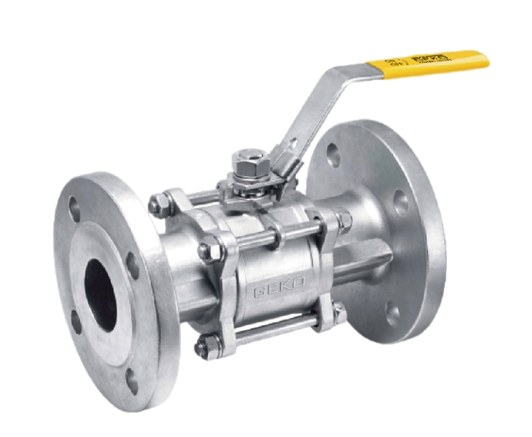
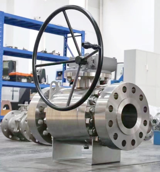
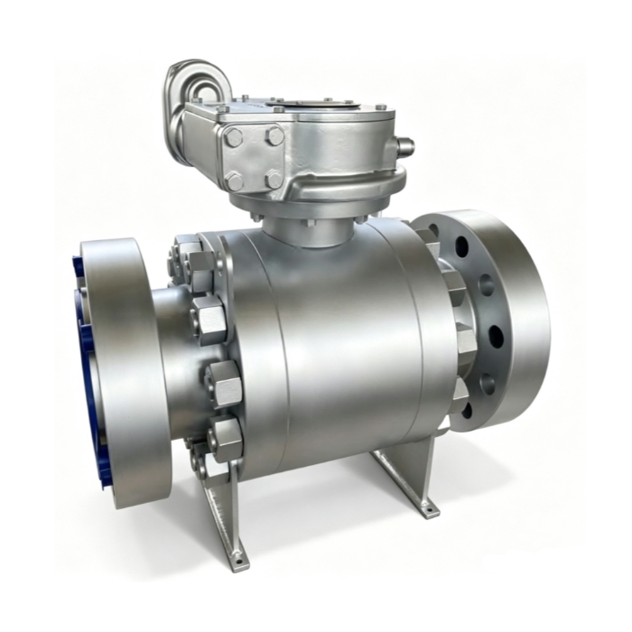
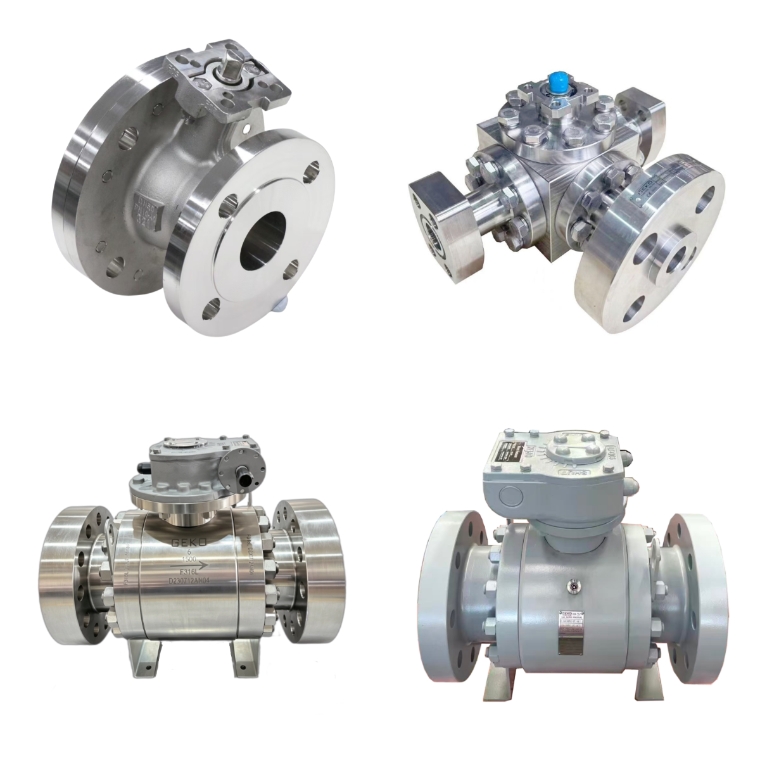
    The Ultimate Guide to Ball Valves and How to Choose Them | GEKO Valve Ball valves are among the most widely used quarter-turn fluid control devices across industrial piping systems. Known for fast operation, reliable sealing, low maintenance and compact structure, they serve critical isolation and flow regulation tasks in water treatment, oil & gas, chemical processing, power generation and many other sectors. This complete guide covers ball valve basics, common types, key specifications and practical selection rules to help you pick the right ball valve for your working conditions. What Is a Ball Valve? A ball valve uses a hollow, perforated rotating ball inside the valve body to control fluid flow. When the ball’s bore aligns with the pipeline, the valve opens and media passes through. Rotating the ball 90 degrees blocks the passage, shutting off flow. Most standard ball valves are designed for tight shut-off, though special designs support throttling service. GEKO Valve delivers a full lineup of ball valves built to deliver dependable sealing and long service life for industrial projects.   Common Types of Ball Valves Floating Ball Valve – The ball is not fixed by upper and lower trunnions. Fluid pressure pushes the ball against the downstream seat to form a seal. Ideal for medium and low pressure applications, simple structure and cost-effective. Trunnion Mounted Ball Valve – The ball is supported by fixed trunnions at top and bottom. Sealing force does not rely fully on line pressure. Suitable for high pressure, large size and heavy-duty industrial pipelines. Top Entry Ball Valve – Maintenance can be carried out directly on site without removing the whole valve from the pipe. Preferred for critical pipelines where shutdown and disassembly are costly. Side Entry (Split Body) Ball Valve – The body is split into two or more parts for easy assembly. Widely used for general industrial and water service. Full Port vs Reduced Port Ball Valve – Full port ball valves have a bore size matching the pipe inner diameter, minimizing flow resistance and pressure drop. Reduced port ball valves feature a smaller bore, lower cost and compact size for non-critical flow loss scenarios. Lined Ball Valve – Lined with PFA, PTFE or other corrosion-resistant materials, for handling strong acids, alkalis and aggressive chemical media. Key Components of a Ball Valve Valve Body: The main pressure-containing shell; common materials include WCB, A105, 304 stainless steel, 316 stainless steel, duplex steel and alloy steel. Ball: The rotating closure member, available in stainless steel, carbon steel, hard-faced alloy for abrasive service. Seat & Sealing Insert: PTFE, RPTFE, Viton, Devlon, metal seat for high temperature or fire-safe requirements. Stem: Transmits torque from the handle or actuator to the ball; anti-blowout stem design is a standard safety feature on GEKO Valve ball valves. Operator: Manual lever, gearbox, pneumatic actuator, electric motor operator (MOV) for automated control. Main Industrial Applications Oil and gas: wellhead isolation, pipeline transmission, refining and storage terminals Chemical industry: corrosive chemical transfer, batch processing and reactor isolation Water treatment: raw water, clean water, sludge and wastewater pipelines Power plants: cooling water, steam auxiliary systems and compressed air lines Food and beverage: sanitary ball valves for hygienic media Hydrogen and clean energy: low-leakage ball valves for hydrogen storage and transportation How to Choose the Right Ball Valve: Step-by-Step Checklist 1. Confirm Media Properties Identify the fluid: water, oil, gas, acid, alkali, slurry or hydrogen. Corrosive media require stainless steel or lined construction. Slurry service needs hard-faced balls and wear-resistant seats to avoid abrasion damage. The technical team at GEKO Valve can assist with material matching for challenging media. 2. Working Pressure and Temperature Match the valve pressure class (Class 150, 300, 600, 900 etc.) to your maximum operating pressure. Check temperature limits: soft seats work well at moderate temperatures, while metal-seated ball valves handle high temperature and fire-safe service. 3. Valve Size and Flow Requirement Select full port if low pressure drop is essential. Reduced port is acceptable when flow loss is not a concern. Confirm connection ends: flange, threaded, butt weld or socket weld to match your piping. 4. Operation Type Manual lever: simple, low cost, for infrequent operation Gear operated: for large size or high torque valves Pneumatic actuator: fast on/off, suitable for automatic control systems Electric actuator: ideal for remote control and slow switching 5. Sealing and Safety Requirements Soft seats provide bubble-tight shut-off for most general service. Metal-to-metal seats are selected for high temperature, fire-safe, abrasive or high cycling conditions. Fire-safe certification and low-emission stem packing are available for hazardous media. 6. Industry Standards Common standards include API 6D, ASME B16.34, ISO 17292. Confirm whether you need special tests such as fugitive emission test, hydrostatic test and cryogenic test. Advantages and Limitations of Ball Valves Advantages 90-degree quick open and close, easy operation Excellent tight shut-off performance Simple structure, fewer wearing parts, long service life Wide range of material options for different media Limitations Standard soft-seated ball valves are not recommended for continuous heavy throttling High temperature may degrade soft seat materials Trunnion and large-size ball valves come with higher cost Final Selection Tips Never choose a ball valve only by nominal size and pressure rating. Always evaluate media corrosion, temperature cycling, actuation frequency and safety codes. If you work with hazardous or high-value media, prioritize certified low-leakage and fire-safe designs. For long-term reliability, match body, ball and seat materials as a complete set rather than mixing incompatible materials. Reach out to GEKO Valve for technical support when you are unsure about your selection. Conclusion Ball valves are versatile, dependable fluid control components, but proper selection directly determines system safety and service life. This guide walks you through core types, construction, application scenarios and critical selection criteria. When you clarify your media, pressure, temperature, operation mode and standard requirements, you can efficiently narrow down the correct ball valve model for your piping project. Target Keywords GEKO ball valve, trunnion ball valve, floating ball valve, stainless steel ball valve, PTFE seat ball valve, fire safe ball valve, full port ball valve, industrial ball valve, low emission ball valve
    ЧИТАТЬ ДАЛЕЕ
  • Ball Valve Materials Guide for Corrosion Resistance and Durability | GEKO Valve
    Ball Valve Materials Guide for Corrosion Resistance and Durability | GEKO Valve
    Oct 20, 2026
    Ball Valve Materials Guide for Corrosion Resistance and Durability Corrosion and premature wear are two leading causes of ball valve failure in chemical processing, offshore, water treatment, and oil & gas piping systems. Selecting the correct ball valve materials directly determines long-term durability, sealing integrity, safety, and total cost of ownership. A ball valve built with incompatible alloys or seat materials can suffer pitting, crevice corrosion, chemical attack, or seal degradation, leading to fugitive emissions, unplanned shutdowns, and expensive replacement. This GEKO Valve guide breaks down body, ball, liner, and seat materials by corrosion performance, service limits, and suitable industrial applications, helping engineers specify valves that last in aggressive process media. Why Corrosion Resistance and Material Durability Matter for Ball Valves Unlike generic piping components, ball valves contain wetted parts that stay in continuous contact with process fluids — acids, alkalis, brine, chlorides, solvents, and sour media. Even minor corrosion can lock the rotating ball, damage sealing surfaces, and break pressure containment. Durability does not only mean mechanical strength; it combines corrosion resistance, temperature stability, abrasion resistance, and resistance to cyclic operation. The optimal material balances chemical compatibility, pressure rating, temperature range, and project budget rather than defaulting to the most expensive superalloy.   Common Ball Valve Body Materials for Corrosive Service WCB Carbon Steel WCB is the standard cast carbon steel for general-purpose ball valves. It delivers high mechanical strength and pressure resistance but offers limited corrosion resistance. Carbon steel is suitable for clean oil, steam, natural gas, and non-corrosive water. In corrosive environments, WCB ball valves rely on internal PTFE or PFA lining to isolate the metal body from aggressive media. Without lining, carbon steel will rust rapidly in damp, acidic, or chloride-rich conditions. 304 / 316L Stainless Steel (CF8 / CF3M) 304 stainless steel works well for low-chloride fresh water, food-grade fluids, and mild alkaline solutions. 316L stainless steel adds molybdenum, greatly improving resistance to chloride ions, dilute acids, wastewater, and common organic solvents. The low-carbon 316L grade avoids intergranular corrosion after welding, making it the most widely specified stainless steel ball valve for moderate corrosion duties. It remains the baseline anti-corrosion choice for water treatment, pharmaceutical, and general chemical lines. 2205 and 2507 Duplex Stainless Steel Duplex stainless steel combines austenite and ferrite microstructures for superior chloride corrosion resistance and higher strength than 316L. 2205 duplex handles brine, brackish water, and moderate seawater service. 2507 super duplex offers outstanding pitting and stress corrosion cracking resistance for seawater desalination, coastal chemical plants, and produced water pipelines where standard 316L will fail over time.   High-Performance Alloys: Hastelloy C276, Monel 400, Inconel 625 Hastelloy C276 resists strong oxidizing acids, chlorine, hypochlorite, and mixed corrosive chemicals, widely used in chlor-alkali and fine chemical processes. Monel 400 provides excellent resistance to hydrofluoric acid and seawater. Inconel 625 is selected for high-temperature corrosive media and thermal fatigue conditions. These nickel-based superalloys deliver extreme corrosion protection but carry a much higher material cost and longer lead times. PTFE / PFA Lined Ball Valves Lined ball valves use a carbon steel or stainless steel shell with a continuous fluoropolymer liner covering all wetted surfaces. PTFE and PFA are nearly chemically inert against most concentrated acids, bases, and aggressive solvents. PFA offers better permeation resistance and higher-temperature stability than PTFE. Lined ball valves are a cost-effective alternative to exotic alloys for strong corrosive media at moderate pressure ranges. Ball and Seat Materials: The Critical Sealing Interface Body alloy protects the valve shell, but the ball and seat form the sealing interface that controls leakage and cycle life. Seat material failure is one of the most frequent durability issues in corrosive ball valves. Virgin PTFE: Universal chemical resistance, compatible with almost all corrosive media. Drawback: cold flow under sustained pressure, which can degrade sealing after long static hold periods. RPTFE (Reinforced PTFE): Filled with glass, carbon, or graphite to reduce creep and boost wear resistance while retaining broad chemical compatibility. It is the most popular upgrade over pure PTFE. PEEK: Excellent combination of corrosion resistance, high temperature capability, and mechanical durability for high-cycle and high-pressure chemical service. Viton / EPDM: Elastomer seats for specific media; Viton suits oils and hydrocarbons, EPDM works for hot water and weak acids. Both are limited against strong solvents and concentrated acids. Metal Seat with Stellite Coating: Hardened metal sealing surfaces for high temperature, abrasive slurry, and fire-safe service. Metal-sealed ball valves rely on alloy selection for corrosion resistance and do not provide bubble-tight shutoff like polymer seats. Key Selection Checklist for Corrosion Resistance & Durability Before finalizing ball valve materials, verify these application parameters: Full chemical composition of the process fluid, including trace chlorides, solids, and oxidizers Operating temperature and pressure, plus upset and thermal cycling conditions Flow velocity and abrasive particles that cause erosion wear Shutoff requirement: bubble-tight soft seat or fire-safe metal seat External environment: coastal salt spray, humid air, or underground burial Maintenance access and expected service life target Common Application Matching Summary Fresh water and mild chemical media → 316L ball valve with RPTFE seat. Seawater and brine → 2205 / 2507 duplex stainless steel. Concentrated acids and aggressive solvents → PFA-lined ball valve. Chlorine and mixed oxidizing chemicals → Hastelloy C276. High-temperature abrasive process → Stellite hard-faced metal seat paired with compatible body alloy. Final Thoughts Durable, corrosion-free ball valve performance comes from matching every wetted component to the process conditions, not just picking a single alloy. GEKO Valve supplies ball valves in carbon steel, stainless steel, duplex, nickel alloy, and PFA/PTFE lined configurations with a full range of seat and ball trim options. Proper material specification reduces corrosion-related failures and extends valve service life in demanding industrial piping systems.
    ЧИТАТЬ ДАЛЕЕ
  • Ball Valve Materials: Pros and Cons for Industrial Applications | GEKO Valve
    Ball Valve Materials: Pros and Cons for Industrial Applications | GEKO Valve
    Oct 14, 2026
    Ball Valve Materials: Pros and Cons for Industrial Applications Selecting ball valve materials requires careful trade-offs between corrosion resistance, temperature tolerance, mechanical strength, cost and manufacturability. No single material works for every industrial process. Understanding the pros and cons of common ball valve body, ball and seat materials helps process engineers avoid premature failure, unexpected leakage and overspending on overly expensive alloys. This guide compares widely used materials for GEKO industrial ball valves to support faster, smarter valve specification. WCB Cast Carbon Steel & A105 Forged Carbon Steel Pros: High tensile strength, good performance under high pressure and elevated temperatures, affordable price, easy welding and machining. A105 forged carbon steel has denser grain structure, better impact resistance than cast WCB, ideal for critical high-pressure lines, steam and hydrocarbon service. Cons: Poor corrosion resistance. Carbon steel rusts rapidly when exposed to moisture, acids, chlorides and most corrosive chemicals. Not suitable for potable water, brine or continuous wet corrosive service. Impact performance drops sharply at cryogenic temperatures. SS304 / CF8 Stainless Steel Pros: Good general corrosion resistance for clean water and weak alkaline media, oxidation-resistant at moderate heat, easy to sanitize, cost-effective stainless option. It is widely accepted for sanitary, food and beverage, municipal water and general outdoor piping systems. Cons: Susceptible to pitting corrosion in chloride-containing environments such as seawater and brine. Poor resistance to strong acids. Not recommended for high-salinity or harsh chemical processes. SS316 / 316L (CF8M / CF3M) Stainless Steel Pros: Molybdenum addition improves chloride and mild acid resistance significantly. 316L low-carbon grade resists intergranular corrosion after welding. Versatile for chemical processing, food production, desalination pre-treatment and marine non-seawater circuits. It is the most popular stainless steel for corrosive industrial service. Cons: Still vulnerable to concentrated chloride, hot brine and strong reducing acids. Higher cost than SS304, and it cannot compete with duplex or nickel alloys for severe corrosion environments. 2205 Duplex Stainless Steel Pros: Combines austenitic and ferritic microstructure for high mechanical strength and excellent chloride pitting resistance. Outperforms 316 in brackish water, brine and low-to-moderate acid conditions. More economical than Hastelloy and other nickel alloys for seawater-related applications. Cons: Limited high-temperature operating range; it loses corrosion resistance at excessive heat. Less ductile than austenitic stainless steel and harder to machine. Not suitable for strong reducing acids. PFA / PTFE Lined Materials Pros: Almost universal chemical inertness against strong acids, alkalis and aggressive solvents. The metal shell provides structural strength while fluoropolymer lining isolates corrosive media. Perfect for harsh chemical processing where standard metals degrade quickly. Cons: Lining can be scratched by abrasive slurries. Not compatible with high-temperature steam. Temperature and pressure ratings are lower than solid metal valves, and lined valves are heavier and more expensive than carbon steel alternatives. Hastelloy C276, Alloy 20 and Monel Nickel Alloys Pros: Outstanding resistance to oxidizing acids, sour gas (H₂S), chlorine and many aggressive chemicals. Excellent resistance to stress corrosion cracking and localized pitting. These specialty alloys serve critical, high-risk processes where 316 and duplex steel fail. Cons: Very high raw material and machining costs. Long lead times are common. Nickel alloys are only justified for extreme corrosive conditions, making them impractical for standard water, oil or steam lines. Common Seat & Seal Materials: PTFE, FKM, Metal, PEEK PTFE: Pros — chemically inert, bubble-tight shutoff; Cons — prone to cold flow, limited high-temperature range. FKM (Viton): Pros — resistant to oils, fuels and hydrocarbons; Cons — incompatible with ketones and some strong acids. Metal seat: Pros — suitable for high temperature, abrasive media and frequent cycling; Cons — not bubble tight, higher torque requirement. PEEK: Pros — excellent wear and high-temperature resistance; Cons — premium pricing, limited availability. Quick Comparison Guidance Carbon steel works best for non-corrosive high-temperature steam and oil. SS304 fits clean, low-chloride water and sanitary light-duty service. SS316 balances performance and budget for general corrosive applications. 2205 duplex is the go-to for brine and high-chloride water. Lined valves handle aggressive chemicals, while nickel alloys are reserved for extreme corrosive process conditions. Closing Notes from GEKO Valve Material selection should never rely on cost alone. A cheaper valve that fails early will generate far higher downtime and maintenance costs. Share your medium, temperature, pressure and chemical concentration with GEKO’s engineering team to select a ball valve material that matches your industrial application perfectly.
    ЧИТАТЬ ДАЛЕЕ
  • Which Ball Valve Material Is Best for Your Application? | GEKO Valve
    Which Ball Valve Material Is Best for Your Application? | GEKO Valve
    Oct 14, 2026
    Which Ball Valve Material Is Best for Your Application? Choosing the correct ball valve material is one of the most critical decisions for process reliability. Even a well-designed ball valve will fail prematurely if its body, ball and seat materials are incompatible with your fluid, temperature, pressure and chemical environment. With options ranging from WCB carbon steel and stainless steel to duplex steel, PFA lining and specialty alloys, engineers and procurement teams need a clear framework to match materials to their exact working conditions. This guide breaks down common ball valve materials, their strengths, limitations and ideal use cases to help you select the right GEKO ball valve for your system. Core Factors That Decide Ball Valve Material Before comparing materials, confirm four key process parameters. The fluid medium and chemical concentration determine corrosion risk. Operating temperature impacts material toughness, creep resistance and seal performance. Working pressure defines wall thickness and mechanical strength requirements. Additional factors include chloride content, abrasive particles, cyclic switching frequency and hygienic requirements for food or pharmaceutical service.     WCB Carbon Steel / A105 Forged Steel Ball Valves WCB cast carbon steel and A105 forged carbon steel are cost-effective, high-strength options for non-corrosive media. They perform reliably at elevated temperatures and suit steam, compressed air, fuel oil and natural gas pipelines in power plants, thermal systems and general oil & gas service. Carbon steel works well from -29°C up to around 425°C, but it rusts quickly when exposed to water, acids or chloride-rich fluids. It is not recommended for wet corrosive service, drinking water or chemical processing lines. SS304 (CF8) Stainless Steel Ball Valves SS304 stainless steel is the standard corrosion-resistant ball valve material for water treatment, clean water, weak alkaline fluids and general outdoor piping. It offers good oxidation resistance and excellent low-temperature toughness, making it popular for general industrial and sanitary applications. SS304 works for low-chloride water but struggles with saltwater, brine and concentrated chloride media, where pitting corrosion will develop over time. SS316 / 316L (CF8M / CF3M) Stainless Steel Ball Valves SS316 stainless steel includes molybdenum, which greatly improves resistance to chlorides, mild acids and many chemical solvents. It is the most widely specified stainless grade for chemical plants, desalination pre-treatment, food & beverage processing and marine non-seawater circuits. 316L low-carbon variants reduce intergranular corrosion after welding, preferred for long-term continuous chemical service. For most general corrosive industrial applications, SS316 is the default upgrade from SS304. 2205 Duplex Stainless Steel Ball Valves 2205 duplex stainless steel combines high mechanical strength and superior chloride pitting resistance. It outperforms 316 in brackish water, seawater, brine and moderate acid environments. Duplex ball valves are widely used in desalination, offshore auxiliary lines and mine water systems. It balances strength and corrosion resistance without moving to expensive nickel alloys, though it has narrower high-temperature limits than many stainless grades. PFA / PTFE Lined Ball Valves PFA and PTFE lined ball valves use a carbon steel or stainless steel pressure shell with a fluoropolymer lining that contacts the fluid. The lining is chemically inert against most strong acids, alkalis and aggressive solvents. These lined ball valves are the primary choice for harsh chemical processes where metallic alloys cannot survive. They are not suitable for high-temperature steam or abrasive slurries that can scratch the lining surface. Specialty Alloy Ball Valves: Hastelloy, Alloy 20, Monel For extreme corrosive conditions such as concentrated acids, sour gas, hydrogen sulphide and oxidising chemicals, GEKO supplies ball valves built from Hastelloy C276, Alloy 20 and Monel. These exotic alloys resist localized corrosion and stress cracking in environments that attack 316 and duplex steel. They carry higher material costs and are reserved for critical chemical, hydrogen and high-risk process applications. Seat & Seal Material Matching (Not Only Body Material) Body material alone cannot guarantee reliable shutoff. Seat materials must also match the process. PTFE seats deliver bubble-tight isolation for most clean fluids up to moderate temperatures. FKM (Viton) works for oils and hydrocarbons. Metal seats are selected for high temperature, abrasive media and frequent cycling. PEEK seats offer outstanding wear resistance for demanding cyclic service. A mismatch between seat material and medium is a common cause of leakage even when the valve body is correctly specified. Quick Application Reference Steam, oil, compressed air: WCB / A105 carbon steel Clean water, food-grade mild fluid: SS304 General chemical, low-chloride corrosive service: SS316 / 316L Seawater, brine, high-chloride water: 2205 duplex stainless steel Strong acids and aggressive chemicals: PFA lined ball valve Sour gas, concentrated corrosive media: Hastelloy or nickel alloy Final Recommendations from GEKO Valve The best ball valve material is always the one that balances corrosion resistance, temperature-pressure rating, service life and budget. Over-specifying exotic alloys increases unnecessary expense, while under-specifying leads to unplanned shutdowns and safety risks. If you are unsure about material compatibility for your process fluid, share your medium, temperature, pressure and concentration data with GEKO’s engineering team for a verified material recommendation.
    ЧИТАТЬ ДАЛЕЕ
  • How Does a Butterfly Valve Open and Close? Full Operating Guide | GEKO Valve
    How Does a Butterfly Valve Open and Close? Full Operating Guide | GEKO Valve
    Oct 09, 2026
    How Does a Butterfly Valve Open and Close? Full Operating Guide Butterfly valves are the most widely used quarter-turn flow control devices in industrial and municipal piping systems. Many engineers and procurement specialists select industrial butterfly valves for their compact size and cost-saving advantages, yet few fully understand the complete mechanical process of how a butterfly valve opens and closes. Unlike linear-stroke gate valves and globe valves, butterfly valves rely on precise rotary motion to change pipeline flow status. This article clearly explains the opening and closing working process, mechanical logic of different valve designs, actuation modes, and sealing coordination principles. 1. Basic Open and Close Principle of Butterfly Valves The entire opening and closing action of a butterfly valve is completed through a 90-degree quarter-turn rotation. The core moving parts include the valve stem and internal butterfly disc. The stem receives torque from manual or automated actuators and drives the disc to rotate horizontally inside the pipeline bore, realizing full opening, full closing, and intermediate throttling states. Closing Process (90° → 0°): The disc gradually rotates perpendicular to the fluid flow direction, continuously narrowing the flow passage. When reaching 0 degrees, the disc completely presses against the valve seat, blocking the pipeline and achieving tight shutoff. Opening Process (0° → 90°): The disc rotates parallel to the fluid direction, gradually expanding the flow area. At 90 degrees, the disc is fully opened, minimizing flow resistance and allowing maximum fluid passage. This simple rotary operation is what makes wafer butterfly valves and lug butterfly valves so popular for large-bore piping. 2. Complete Mechanical Action Process   The opening and closing cycle follows a fixed mechanical transmission chain, ensuring accurate and stable operation: First, the operating device (lever, gearbox, pneumatic or electric actuator) outputs rotational torque. The torque is transmitted to the central valve stem through the driving shaft. The integrated stem and disc structure rotates synchronously without idle travel. During movement, the disc gradually separates from or compresses against the sealing seat. Finally, the mechanical limit device locks the angle to complete opening or closing positioning. 3. Different Opening & Closing Logic by Valve Structure Concentric and offset butterfly valves have obvious differences in opening and closing friction, which directly affects service life and operating stability: 3.1 Concentric Butterfly Valve Operation Concentric butterfly valves have overlapping centers of the stem, disc, and pipeline. During every opening and closing stroke, the disc keeps continuous contact and friction with the seat. The operation is simple and cost-effective, suitable for low-frequency switching of conventional water treatment and HVAC pipelines. 3.2 Triple Offset Butterfly Valve Zero-Friction Operation Triple offset butterfly valves adopt a three-dimensional offset structure. During the opening process, the disc instantly separates from the seat without friction. During closing, the disc only contacts the seat at the final locking position. This zero-friction opening and closing mechanism greatly reduces seat wear, making this style of heavy duty butterfly valves suitable for high-temperature, high-pressure, and frequent switching industrial pipelines. 4. Sealing Coordination During Opening and Closing Different sealing types match different opening and closing mechanical characteristics: 4.1 Soft Seated Butterfly Valve Soft seated butterfly valves with EPDM or NBR seats rely on elastic compression to achieve zero leakage when fully closed. During closing, the disc gently squeezes the elastic seat to fill tiny gaps. During opening, the elastic seat resets automatically. This flexible sealing opening and closing mode ensures bubble-tight shutoff for clean water and gas media. 4.2 Metal Seated Butterfly Valve Metal seated butterfly valves adopt precision metal-to-metal matching. The opening and closing process realizes rigid mechanical fitting and separation. With high wear resistance and temperature resistance, they maintain stable switching performance in harsh working conditions such as high-temperature steam and abrasive slurry. 5. Opening and Closing Modes of Automated Butterfly Valves Modern industrial pipelines use automated butterfly valves to realize intelligent opening and closing control: Pneumatic Butterfly Valve: Driven by compressed air, it completes fast opening and closing strokes in seconds. With explosion-proof advantages, it is widely used in chemical and petrochemical pipeline switching. Electric Butterfly Valve: Driven by electric actuators, it features stable speed, precise angle positioning, and remote signal control. It supports delayed opening/closing and intermediate positioning, suitable for intelligent pipeline systems. Manual Butterfly Valve: Operated by lever or gear handwheel, it realizes on-site manual opening and closing, economical and convenient for low-frequency operation scenarios. 6. Common Opening & Closing Faults and Causes Valve jamming: Caused by sediment deposition, seat aging, or insufficient actuator torque Incomplete closing and leakage: Disc offset, seat wear, or foreign matter blocking the sealing surface Slow opening and closing speed: Pneumatic air pressure insufficiency or electric actuator parameter deviation 7. GEKO Valve Precise Opening & Closing Performance All GEKO butterfly valves adopt optimized rotary motion structure, ensuring flexible, smooth, and accurate opening and closing actions. Our full product range including wafer, lug, soft seat, metal seat, and triple offset butterfly valves achieves zero-friction switching, stable sealing, and long service life. Automated modulating butterfly valves support arbitrary angle opening and closing, meeting isolation and throttling control requirements of modern industrial piping systems.
    ЧИТАТЬ ДАЛЕЕ
  • What Is the Role of a Butterfly Valve in Piping Systems? | GEKO Valve
    What Is the Role of a Butterfly Valve in Piping Systems? | GEKO Valve
    Oct 09, 2026
    What Is the Role of a Butterfly Valve in Piping Systems? Industrial and municipal piping networks transport liquids, gases and slurries across vast facilities, requiring reliable flow control hardware to keep operations safe and predictable. As a popular quarter-turn valve, the butterfly valve performs multiple core functions within piping systems. Its compact build, lightweight body and flexible operating modes make it a go-to choice for many pipeline designs, from large water mains to chemical processing lines. This article breaks down the key roles butterfly valves play in piping systems and where their strengths shine. 1. Fluid Isolation for Pipeline Maintenance & Emergency Shutoff One primary role of a butterfly valve is positive isolation. When a pipe segment, pump or downstream equipment needs inspection or repair, operators close the butterfly valve to fully cut off fluid flow. In emergency scenarios such as pipeline overpressure or equipment failure, it can rapidly shut down the line to prevent spillage and system damage. Lug and flange butterfly valves are commonly used for isolation duties, with PTFE or EPDM seats delivering tight shutoff performance. 2. Flow Throttling and Flow Regulation Beyond simple on/off service, butterfly valves are widely used for throttling flow. By rotating the disc to partial opening positions, the valve adjusts the cross-sectional flow area, controlling the volume and velocity of fluid moving through the piping. This function helps stabilize pressure and maintain consistent flow rates for processes like water distribution, HVAC circulation and chemical transfer. Note that precise throttling requires proper material selection to avoid disc erosion from high-speed media. 3. Pressure Control and Surge Mitigation Butterfly valves assist in managing pipeline pressure. Gradual opening or closing can moderate pressure spikes caused by pump start-up and shutdown. In large-diameter piping systems, slow-actuated butterfly valves help reduce water hammer effects that may damage pipe fittings and instruments. Pneumatic or electric actuators are often paired with butterfly valves for automated pressure regulation in modern piping networks.   4. Diversion and Flow Direction Switching In multi-branch piping layouts, sets of butterfly valves work together to divert fluid to different branches. For example, in water treatment plants, they switch flow between filter banks, or in district heating systems, they redirect hot water to different building zones. This eliminates the need to shut down the entire piping system when rerouting process media. 5. Backflow Prevention (Auxiliary Function) While butterfly valves are not dedicated check valves, properly specified butterfly valves can help limit unwanted reverse flow in certain low-risk piping applications. For critical backflow protection, they are usually combined with dedicated check valves as part of a complete piping safety assembly. Key Benefits of Butterfly Valves for Piping Networks Space-saving design: Much thinner than gate or globe valves, ideal for tight pipe rack installations Light weight: Reduces structural load on pipe supports, lowering overall project cost Fast quarter-turn operation: Manual lever, gear, pneumatic or electric actuation options available Wide size range: Works for both small process lines and large diameter main pipelines Corrosion-resistant options: Lined butterfly valves available for corrosive chemical media Selection Tips According to Piping Roles Choose resilient seated butterfly valves for water and wastewater isolation tasks. For corrosive fluids, PTFE lined butterfly valves are recommended. If automatic control is required, specify pneumatic or electric actuators to integrate with plant control systems. Confirm pressure class, flange standard and seat material to match your piping medium and operating temperature. Summary Within piping systems, butterfly valves serve five major purposes: fluid isolation, flow throttling, pressure management, flow diversion and auxiliary backflow control. Thanks to their compact footprint and versatile actuation choices, butterfly valves deliver dependable flow control across water, chemical, power and HVAC piping networks. Selecting the correct butterfly valve design ensures stable, long-term pipeline operation and reduces unplanned downtime.
    ЧИТАТЬ ДАЛЕЕ
  • How Do Butterfly Valves Work in Water Treatment Plants? | GEKO Valve
    How Do Butterfly Valves Work in Water Treatment Plants? | GEKO Valve
    Oct 09, 2026
    How Do Butterfly Valves Work in Water Treatment Plants? Water treatment facilities rely on stable, cost-effective flow control equipment to manage raw water intake, chemical dosing, filtration, disinfection and effluent discharge. Butterfly valves are widely preferred across all stages of water treatment thanks to their compact size, fast quarter-turn operation, light weight and competitive pricing. Compared with bulky gate valves, butterfly valves save installation space and reduce structural load for large-diameter pipelines commonly seen in water plants. This article explains how butterfly valves function in key water treatment processes and their practical operational advantages. Core Working Principle for Water Treatment Service A butterfly valve uses a circular disc mounted on a central shaft. When the valve rotates 90 degrees, the disc turns parallel or perpendicular to fluid flow. At the fully open position, water flows with minimal resistance; at the closed position, the disc presses against the seat to shut off flow. Between open and closed angles, partial rotation enables throttling for controlled water flow rates. Most water treatment butterfly valves use resilient rubber seats such as EPDM, delivering bubble-tight shutoff for clean and wastewater media.   Typical Applications Inside Water Treatment Plants 1. Raw Water Intake & Pump Station Butterfly valves are installed at intake lines and pump outlets to isolate pipelines during pump maintenance. They quickly cut off raw water from rivers, lakes or reservoirs, protecting downstream filtration units. Large wafer or lug type butterfly valves are commonly selected here due to easy installation between pipe flanges. 2. Coagulation, Flocculation and Sedimentation Tanks Within sedimentation basins, butterfly valves regulate flow between treatment chambers. Operators adjust the disc angle to balance water velocity, supporting stable floc formation and solid settling. Manual or gear-operated versions are widely used for frequent on-off and moderate throttling tasks. 3. Filtration Systems Sand filters and activated carbon filter banks use butterfly valves to switch between filtration and backwash cycles. The valves isolate individual filter units so one tank can undergo backwashing without shutting down the whole treatment line. EPDM seats resist wear from periodic flushing and particle-laden water. 4. Disinfection and Chemical Dosing Lines For chlorine, sodium hypochlorite or pH adjustment chemical pipelines, lined butterfly valves prevent corrosion from chemical additives. They provide reliable isolation for maintenance of dosing skids and mixing chambers. 5. Effluent Discharge and Wastewater Outlet Before treated water is released, butterfly valves control discharge flow and act as emergency shutoff devices. Lug style butterfly valves are often chosen for end-of-line service, allowing blind flange isolation when required. Key Selection Considerations for Water Treatment Butterfly Valves Seat material: EPDM is standard for clean water; choose stronger wear-resistant seats for wastewater with suspended solids Body material: Ductile iron is the mainstream cost-effective option for water projects Actuation: Manual gearbox for occasional operation; pneumatic or electric actuators for automated plant SCADA control Pressure rating: Match pipeline working pressure and surge pressure from pump startup and shutdown Valve type: Wafer butterfly valves for compact installation; lug butterfly valves for dead-end service Advantages of Butterfly Valves in Water Plants Their lightweight design lowers pipeline support costs, while fast quarter-turn operation speeds up emergency shutdown. They are easy to automate for modern smart water plants, and require less maintenance than many alternative valves. The main limitation is that standard resilient seated butterfly valves are not suitable for high-pressure steam or highly abrasive heavy slurry, which needs other valve solutions. Summary From raw water intake through filtration, chemical treatment to final discharge, butterfly valves serve as versatile flow isolation and throttling components across the full water treatment workflow. Properly sized butterfly valves with suitable seat and body materials help water plants maintain stable operation, reduce downtime and cut overall project and maintenance costs.
    ЧИТАТЬ ДАЛЕЕ
  • What Is a Butterfly Valve and What Are Its Key Components? | GEKO Valve
    What Is a Butterfly Valve and What Are Its Key Components? | GEKO Valve
    Sep 29, 2026
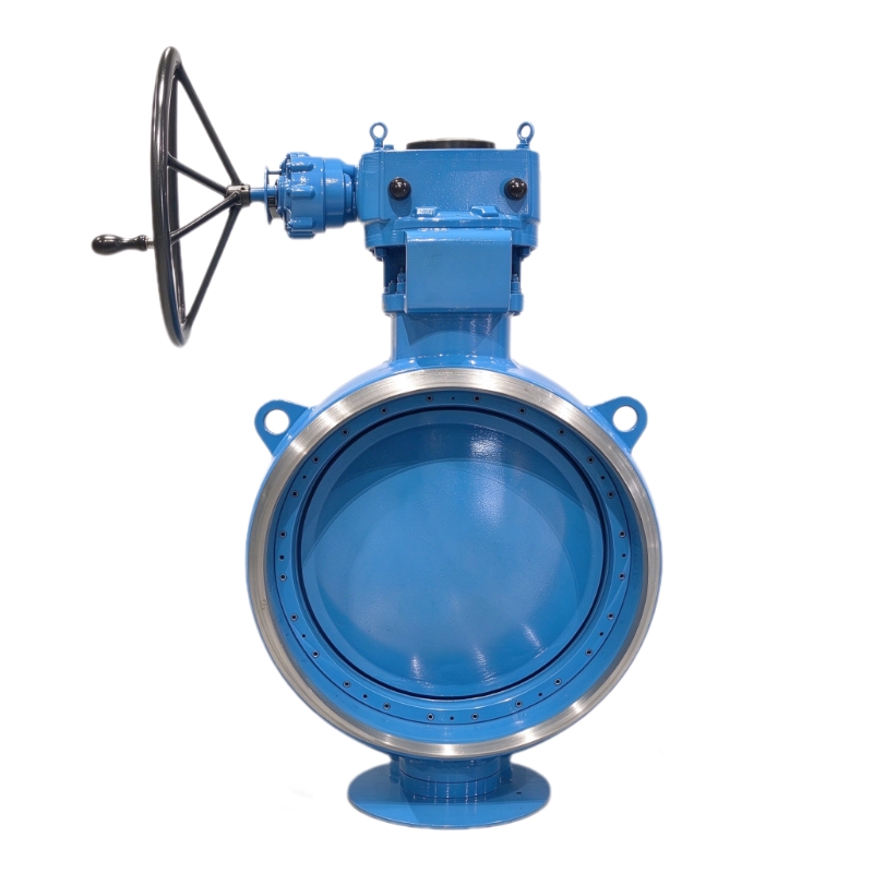
      What Is a Butterfly Valve and What Are Its Key Components? A butterfly valve is a popular quarter-turn flow control device widely used in municipal and industrial piping systems to regulate, throttle, or completely shut off fluid flow. Its slim, lightweight design makes it far more space-saving than ball valves or gate valves, especially for large-diameter pipelines. Many new buyers and plant engineers want to understand exactly what a butterfly valve is and how each internal part works together to deliver reliable performance. This article breaks down the definition, core function, and all key components of a butterfly valve.   Definition and Core Function of a Butterfly Valve At its simplest, a butterfly valve controls fluid by rotating a circular disc inside the pipeline. A 90-degree rotation switches the valve between fully open and fully closed positions. It can also stay at intermediate angles for throttling flow. Wafer butterfly valves and lug butterfly valves are the two most common body styles, while offset designs like triple offset butterfly valves handle demanding high-temperature and high-pressure applications. Butterfly valves work with water, air, gas, and many chemical media across water treatment, HVAC, power, and chemical processing industries. Key Components of a Butterfly Valve 1. Valve Body The valve body forms the main pressure-containing shell and connects to the pipeline. Wafer-style bodies fit between two pipe flanges without bolt lugs. Lug bodies have threaded lugs built into the valve to hold flanges securely. Heavy-duty metal seated butterfly valves use cast iron, ductile iron, stainless steel, or alloy steel bodies to withstand harsh working environments. 2. Butterfly Disc The disc is the circular plate inside the body that blocks or allows fluid passage. It rotates with the valve stem. The disc shape directly impacts flow resistance. Concentric valves use a flat disc; double offset and triple offset valves use contoured discs to reduce seat friction during rotation. For corrosive media, discs are coated or made from stainless steel to extend service life. 3. Valve Stem The stem is a shaft that passes through the valve body and attaches firmly to the disc. It transfers torque from the actuator or handwheel to rotate the disc. Most stems are made of high-strength stainless steel to resist torsion and corrosion. Many designs use a one-piece stem and disc connection to eliminate play and improve control precision. 4. Seat / Sealing Ring The seat creates the sealing contact surface between the disc and valve body. Soft seated butterfly valves use elastomer seats such as EPDM or PTFE to achieve bubble-tight shutoff for clean media. Metal seated versions use metal-to-metal sealing surfaces, suited for high temperature, abrasive, or steam media where rubber seats cannot survive.   5. Stem Seals & Gaskets Stem seals prevent fluid leakage along the stem where it exits the valve body. Packing rings or O-rings form the primary barrier. They are critical to prevent fugitive emissions, especially for chemical and oil & gas applications. 6. Actuator / Operating Unit The actuator supplies torque to turn the stem and disc. Manual versions use a handwheel or lever. Pneumatic butterfly valves use compressed air for fast on/off or modulating control. Electric butterfly valves allow remote automated operation and precise flow adjustment. Positioners can be fitted to modulating actuators to maintain exact disc angles. How These Components Work Together When the actuator turns the valve stem, the disc rotates inside the body. In closed position, the disc presses against the seat to block fluid. When opened, the disc turns parallel to flow so media can pass through. All parts must be properly matched to the working pressure, temperature, and medium. A mismatch in seat or disc material will quickly cause leakage and premature failure. GEKO Valve Butterfly Valve Range GEKO Valve supplies complete butterfly valve assemblies with high-quality components. Our range includes soft seated and metal seated, concentric, double offset and triple offset butterfly valves, available in wafer, lug, flanged designs with manual, pneumatic or electric actuators for industrial and municipal projects worldwide. 9 Core SEO Keywords: Wafer Butterfly Valve, Lug Butterfly Valve, Triple Offset Butterfly Valve, Soft Seated Butterfly Valve, Metal Seated Butterfly Valve, Pneumatic Butterfly Valve, Electric Butterfly Valve, Automated Butterfly Valve, Heavy Duty Butterfly Valve
    ЧИТАТЬ ДАЛЕЕ
  • How Does a Butterfly Valve Control Fluid Flow? Complete Working Guide | GEKO Valve
    How Does a Butterfly Valve Control Fluid Flow? Complete Working Guide | GEKO Valve
    Sep 29, 2026
      How Does a Butterfly Valve Control Fluid Flow? Complete Working Guide Butterfly valves are widely recognized as the most cost-effective and space-efficient fluid control devices for municipal and industrial pipelines. Unlike ball valves that provide full straight-line flow or gate valves designed only for full open or full closed isolation, industrial butterfly valves feature unique rotary disc mechanics that enable flexible fluid management. Many system designers and plant operators wonder: how does a butterfly valve control fluid flow accurately and stably? This guide explains the full flow control mechanism, different working states of butterfly valves, structural differences between product types, and practical flow control performance in modern piping systems. 1. Basic Fluid Control Principle of Butterfly Valves The core fluid control method of a butterfly valve relies on a90-degree quarter-turn rotary disc. Installed vertically in the pipeline center, the butterfly disc rotates along the valve stem to change the effective flow area inside the pipe. By adjusting the disc angle, the valve precisely changes flow resistance, fluid velocity, and pipeline pressure, thereby realizing three core flow control functions: full flow passage, partial throttling, and complete fluid shutoff. This simple and reliable rotary flow control method is the key reason why wafer butterfly valves, lug butterfly valves, and offset butterfly valves are widely used in large-diameter water, gas, and low-viscosity process fluid pipelines. 2. Three Core Flow Control States 2.1 Full Flow Open State When the disc rotates 90 degrees and is parallel to the fluid direction, the pipeline reaches maximum flow capacity. Although the disc remains inside the pipeline, the streamlined disc structure minimizes flow resistance. In this state, the industrial butterfly valve allows unrestricted fluid transmission, suitable for long-term circulating pipeline operation and maximum flow supply scenarios. 2.2 Precise Throttling and Flow Regulation State The biggest advantage of butterfly valves in fluid control is their excellent throttling performance. When the disc stays at any angle between 20% and 70% opening, it forms an adjustable shielding area inside the pipeline. The larger the shielding area, the higher the flow resistance and the lower the fluid flow rate. Modulating butterfly valves with electric or pneumatic actuators can maintain stable opening angles, realizing continuous and accurate flow balancing, pressure adjustment, and fluid distribution control for industrial systems.   2.3 Full Closed Fluid Shutoff State When the disc rotates to 0 degrees and is completely perpendicular to the fluid flow, the disc closely fits the valve seat to block the entire flow passage. Soft seated butterfly valves use elastic seat deformation to achieve bubble-tight zero leakage for clean media, while metal seated butterfly valves rely on precision metal fitting to block high-temperature, high-pressure and abrasive fluids, achieving reliable pipeline isolation and fluid cut-off. 3. How Different Butterfly Valve Types Optimize Flow Control Different butterfly valve structures deliver completely different fluid control effects, adapting to diverse industrial working conditions: 3.1 Concentric Butterfly Valves for General Flow Control Concentric butterfly valves feature coincident stem, disc and pipeline centers, providing stable basic flow regulation and isolation. They are ideal for conventional water treatment, HVAC, and fire protection pipelines with normal temperature and low pressure, offering economical and practical fluid control performance. 3.2 Double and Triple Offset Butterfly Valves for Heavy-Duty Flow Control Triple offset butterfly valves and double offset butterfly valves adopt a unique offset structure. The disc avoids friction with the seat during rotation, ensuring smooth and stable angle adjustment even under high pressure and high temperature. These heavy duty butterfly valves provide precise flow control for steam, flue gas, corrosive chemical media, and high-cycle industrial process pipelines. 3.3 Wafer vs Lug Type Flow Control Features Wafer butterfly valves feature ultra-thin bodies with low flow resistance, suitable for compact pipeline systems requiring stable large-flow control. Lug butterfly valves support unilateral pipeline disassembly while maintaining system flow control safety, facilitating segmented pipeline maintenance without affecting the overall fluid system. 4. How Actuators Support Accurate Fluid Control Stable fluid control cannot be achieved by the valve body alone; the actuator determines control accuracy and automation level: Manual Butterfly Valves: Realize simple on-site flow adjustment and pipeline isolation, suitable for low-frequency control scenarios. Pneumatic Butterfly Valves: Equipped with positioners to correct angle deviation, maintaining stable flow rate under fluctuating pipeline pressure, ideal for explosion-proof industrial fluid systems. Electric Automated Butterfly Valves: Support remote signal adjustment and proportional flow control, matching intelligent industrial systems to realize automatic fluid management and precise flow distribution. 5. Key Advantages of Butterfly Valve Fluid Control Achieve dual functions of fluid isolation and flow throttling with a single valve device Suitable for large-diameter pipeline flow control with low cost and small installation space Smooth rotary operation ensures stable fluid adjustment without pipeline surge Multiple product types adapt to clean, corrosive, high-temperature and abrasive fluid media Support manual and automatic intelligent fluid control for modern industrial systems 6. GEKO Valve Reliable Fluid Control Butterfly Valve Solutions GEKO Valve provides a full range of high-performance butterfly valves for precise industrial fluid control. Our product lineup includes soft seated and metal seated butterfly valves, concentric and triple offset butterfly valves, wafer and lug type butterfly valves, as well as manual, pneumatic and electric automated butterfly valves. All products deliver stable flow regulation, reliable shutoff performance and long service life, providing accurate and efficient fluid control solutions for water treatment, HVAC, chemical, power, and municipal engineering systems. 9 Core SEO Keywords: Industrial Butterfly Valve, Triple Offset Butterfly Valve, Soft Seated Butterfly Valve, Metal Seated Butterfly Valve, Wafer Butterfly Valve, Lug Butterfly Valve, Modulating Butterfly Valve, Heavy Duty Butterfly Valve, Automated Butterfly Valve
    ЧИТАТЬ ДАЛЕЕ
  • Каков механизм работы поворотного затвора? | Клапан GEKO
    Каков механизм работы поворотного затвора? | Клапан GEKO
    Sep 21, 2026
     Каков механизм работы поворотного затвора?Запорные вентили типа «бабочка» — одни из самых универсальных четвертьоборотных регулирующих клапанов, используемых в современных промышленных и коммунальных трубопроводных системах. Большинство инженеров знакомы с быстрым переключением и компактной конструкцией таких вентилей. промышленные поворотные затворыМногие не до конца понимают полный механический механизм работы, обеспечивающий надежную изоляцию жидкости, устойчивость к давлению и точную модуляцию потока для различных типов поворотных затворов. В отличие от шаровых клапанов, использующих сферическое шаровое уплотнение, или задвижек с вертикальным ходом, поворотные затворы используют уникальную механическую структуру с вращающимся диском. В данной статье подробно анализируется полный механический механизм работы поворотных затворов, включая передачу крутящего момента, логику движения диска, механику уплотнения поворотных затворов с мягким и металлическим седлом, принципы работы со смещением и координацию приводов для автоматизированных поворотных затворов.1. Общий обзор механизма механического управленияВесь механизм работы поворотного затвора основан на роторная механическая передача и гидродинамическое согласованиеИсполнительный механизм выдает вращающий момент, который передается через шток клапана для привода внутреннего дискового привода, совершающего четвертьоборотное вращение на 90 градусов. Изменяя угол наклона диска внутри трубопровода, клапан изменяет площадь поперечного сечения потока, тем самым реализуя три основные механические функции: перекрытие потока, обеспечение полного прохождения потока и промежуточное регулирование дросселирования. Вся механическая конструкция отличается меньшим количеством передаточных частей, более простой логикой движения и более быстрым откликом по сравнению с многоходовыми промышленными клапанами.2. Основной механический механизм передачи Передача крутящего момента является основным источником энергии для работы дроссельной заслонки. Полная механическая трансмиссионная цепь состоит из привода, штока клапана, штифта вала и диска дроссельной заслонки, обеспечивая точное преобразование энергии и передачу движения.Когда привод получает сигнал на открытие или закрытие, он генерирует вращающий момент и передает его на вертикальный шток клапана. Шток клапана крепится к дроссельной заслонке с помощью прецизионных штифтов, что исключает холостое вращение и обеспечивает синхронное изменение угла поворота. Вал штока использует высокоточные втулки и уплотнительные прокладки для снижения трения, обеспечивая гибкое и стабильное вращение без заклинивания. Этот механический механизм передачи преобразует электрическую, пневматическую или ручную энергию в механическое вращение, эффективно выполняя операции открытия и закрытия клапана.3. Механический механизм управления потоком дискаДиск-бабочка является исполнительным компонентом системы управления потоком жидкости, и его угловое смещение напрямую определяет состояние потока в трубопроводе. Различные углы открытия соответствуют совершенно различным состояниям механического управления потоком.В закрытом положении (0 градусов) диск полностью перпендикулярен направлению потока жидкости, образуя сплошной барьер против среды. Под действием давления среды диск плотно прилегает к седлу клапана, обеспечивая механическое уплотнение. В полностью открытом положении (90 градусов) диск параллелен направлению потока жидкости, минимизируя сопротивление потоку и обеспечивая максимальный проход жидкости. При любом угле от 0 до 90 градусов диск образует перекрывающуюся дросселирующую структуру с внутренним диаметром трубопровода, используя механическое перекрытие для изменения скорости и давления потока, обеспечивая непрерывное регулирование потока.4. Механизм герметизации (мягкая и жесткая герметизация)Надежная герметичность дисковых затворов обеспечивается двумя различными механизмами механического уплотнения, применимыми в различных промышленных условиях: 4.1 Механизм эластичного сжатия для герметизации (мягкое сиденье)Поворотные затворы с мягким уплотнением В клапанах используются эластичные полимерные седла, такие как EPDM и Viton. Во время хода закрытия диск механически сжимает эластичное седло, вызывая микроупругое деформирование. Деформированное седло заполняет крошечные механические зазоры между краем диска и корпусом клапана, обеспечивая герметичность без утечек. Этот механический механизм упругой компенсации адаптируется к незначительным допускам обработки и изменениям давления в трубопроводе, обеспечивая плотное закрытие задвижек с мягким седлом при нормальной температуре и низком давлении.4.2 Прецизионный механический притирочный уплотнительный механизм (металлическое седло)Поворотные затворы с металлическим уплотнением В клапане используется жесткий металлический уплотнительный механизм. После прецизионной обработки и зеркальной притирки диск и седло образуют высокоточную уплотнительную пару. Благодаря жесткому механическому контакту и силе самозатягивания при среднем давлении клапан обеспечивает стабильное уплотнение в условиях высоких температур, высокого давления и абразивной обработки. Эта механическая уплотнительная конструкция не подвержена деформации при старении и поддерживает длительную высокоцикловую эксплуатацию в промышленных условиях для тяжелых дисковых задвижек.5. Смещенный поворотный затвор с нулевым трением и механическим механизмомКонцентрические и смещенные поворотные затворы имеют принципиальные различия в логике механического управления, что определяет срок службы и устойчивость к давлению.Концентрические поворотные затворы имеют полностью совпадающие центры штока, диска и трубопровода. Диск постоянно трется о седло во время каждого цикла открытия и закрытия, что приводит к быстрому износу седла. В отличие от них, путешествиеле смещение Поворотные затворы В двухстворчатых поворотных затворах используется пространственная смещенная механическая конструкция. На начальном этапе вращения диск автоматически отделяется от уплотнительного седла без трения. Только при достижении конечного угла закрытия диск соприкасается с седлом для позиционирования и герметизации. Этот механизм работы с нулевым трением значительно снижает износ компонентов, повышает долговечность клапана и адаптируется к условиям интенсивной эксплуатации с частыми переключениями для поворотных затворов.6. Автоматизированный механизм координации исполнительных механизмовРазличные исполнительные механизмы формируют различные механизмы автоматического управления, соответствующие современным интеллектуальным трубопроводным системам:Пневматический механизм задвижки типа «бабочка»Преобразует энергию давления сжатого воздуха в механический вращающий момент, отличается быстрым срабатыванием и взрывозащищенными механическими характеристиками, подходит для опасных промышленных сред.Электрический задвижной механизмИспользуется моторный привод и усиление крутящего момента редуктора для достижения точного позиционирования по углу, с поддержкой дистанционного управления сигналом и пропорционального регулирования.Механизм ручного поворотного затвораОснован на ручном механическом вводе крутящего момента, имеет простую конструкцию трансмиссии, стабильна и надежна при работе на низких частотах.7. Промышленные преимущества механического механизма поворотного затвора.Уникальная механическая конструкция обеспечивает промышленный Поворотные затворы Обладая незаменимыми промышленными преимуществами: компактная механическая компоновка экономит место для установки дисковых и фланцевых задвижек, простая конструкция трансмиссии снижает частоту отказов, механизм смещения с нулевым трением продлевает срок службы трехпозиционных дисковых задвижек, а гибкое угловое перемещение обеспечивает двойную функцию изоляции и дросселирования для регулирования работы дисковых задвижек. Эти механические характеристики делают различные типы дисковых задвижек предпочтительным решением для промышленных и коммунальных систем управления потоками больших диаметров.8. Клапан GEKO: высокоточная механическая конструкция.Компания GEKO Valve оптимизирует внутренний механический механизм работы всех промышленных поворотных затворов. Благодаря применению технологий прецизионного литья, обработки на станках с ЧПУ и зеркальной притирки, наши дисковые затворы с плоскими и поперечными выступами, а также затворы с металлическим и мягким уплотнением отличаются равномерной передачей крутящего момента, гибким вращением, точным позиционированием диска и стабильными герметизирующими свойствами. Полный ассортимент продукции, включая концентрические, двухстворчатые и трехстворчатые поворотные затворы, полностью отвечает требованиям к механическому управлению различными промышленными трубопроводами низкого, среднего и высокого давления.9 основных SEO-ключевых словПромышленные поворотные затворы, поворотные затворы с тройным смещением, поворотные затворы с мягким седлом, поворотные затворы с металлическим седлом, дисковые поворотные затворы, поворотные затворы с проушинами, модулирующие поворотные затворы, поворотные затворы повышенной прочности, автоматизированные поворотные затворы
    ЧИТАТЬ ДАЛЕЕ
  • Как задвижки регулируют поток в современных системах?
    Как задвижки регулируют поток в современных системах?
    Sep 21, 2026
    Как задвижки-бабочки регулируют поток в современных системах?Современные промышленные и коммунальные гидравлические системы требуют надежных компонентов, способных как к перекрытию потока, так и к точной модуляции расхода. Среди четвертьоборотных клапанов выделяются поворотные задвижки, отличающиеся компактными размерами, экономичностью и доказанной эффективностью регулирования расхода в трубопроводах большого диаметра. Хотя многие пользователи ассоциируют поворотные задвижки только с простым перекрытием потока, правильно подобранные задвижки могут обеспечивать стабильное дросселирование для жидкостей, газов и сред с низкой абразивностью. В этой статье подробно объясняется, как именно поворотные задвижки регулируют поток, их характеристики управления, подходящие диапазоны рабочих режимов, подбор привода и реальные ограничения в современных технологических системах.Основной механизм регулирования потока в дисковых затворахЗапорный клапан типа «бабочка» регулирует поток путем вращения круглого диска внутри трубы. Диск вращается вокруг центрального вала, соединенного с ручным, пневматическим или электрическим приводом. Когда диск расположен параллельно оси трубопровода, клапан полностью открывается для обеспечения максимальной пропускной способности. По мере вращения диска в сторону закрытого положения он перекрывает часть проходного отверстия, создавая переменное сопротивление потоку, которое регулирует скорость среды и объемный расход. При повороте на 90 градусов диск располагается перпендикулярно потоку для обеспечения перекрытия потока. В отличие от шаровых кранов, обеспечивающих практически беспрепятственный поток по всему диаметру, заслонка всегда остается внутри потока даже при полном открытии. Это неизбежное препятствие создает падение давления, которое становится ключевой физической основой для дросселирования и регулирования потока.Характеристики расхода дисковых затворовБольшинство стандартных поворотных затворов имеют следующую конструкцию: модифицированная характеристика равнопроцентного потокаНебольшие угловые регулировки в среднем диапазоне хода приводят к относительно большим изменениям объема потока. Это означает, что наилучшая эффективность регулирования потока обычно достигается при открытии диска на 20–70%. Работа в положениях, близких к полностью закрытому или почти полностью открытому, снижает точность регулирования: в положениях, близких к закрытому, существует риск кавитации и высокоскоростной эрозии; в положениях, близких к полностью открытому, изменение потока минимально даже при значительном вращении диска.Для сложных контуров управления специально разработанные диски позволяют корректировать кривые расхода в соответствии с линейными требованиями процесса, повышая стабильность в приложениях с непрерывной модуляцией потока.Выбор исполнительного механизма для точного регулирования потокаХорошие результаты регулирования дроссельной заслонки зависят не только от конструкции корпуса клапана, но и от совместимости привода:Ручные поворотные задвижки: Подходит только для грубой, нечастой ручной регулировки; не поддерживает автоматическое управление потоком в замкнутом контуре.Пневматические приводы с позиционерами: Наиболее предпочтительный в отрасли вариант для регулирования режима работы. Позиционеры клапанов преобразуют управляющие сигналы в точные углы поворота диска, компенсируя колебания технологического давления и трение вала.Электрические модулирующие актуаторы: Идеально подходит для объектов без подачи сжатого воздуха, обеспечивая повторяемость позиционирования для современных систем дистанционного управления.Без специального позиционера даже высококачественные поворотные затворы не могут поддерживать стабильный заданный расход при переменном давлении на входе.Основные ограничения при использовании поворотных затворов для регулирования потока. Инженеры должны понимать практические ограничения, чтобы избежать преждевременного выхода компонентов из строя:Длительное дросселирование в почти закрытом положении может вызывать кавитацию, вибрацию, дребезжание диска и износ уплотнений.Абразивные абразивные среды могут быстро разрушать кромки дисков и уплотнительные поверхности в условиях высокоскоростного дросселирования.Запорные вентили типа «бабочка» не рекомендуются для высокоточных систем управления с критическим контуром, где традиционным выбором остаются шаровые вентили.Высокий перепад давления на частично закрытом диске создает значительные крутящие моменты, что требует выбора привода с запасом по мощности.Типичные примеры применения регулирующих задвижек типа «бабочка» в современных системахЗапорные вентили типа «бабочка» широко используются для регулирования потока в крупногабаритных системах, где преобладают ограничения по стоимости и занимаемому пространству:Водоочистные сооружения: регулирование подачи сырой воды, дросселирование распределительного трубопровода.Системы централизованного тепло- и холодоснабжения: балансировка потоков горячей и охлажденной воды.Нефтехимические установки: модуляция контура охлаждающей воды, регулировка потока низкокоррозионного газа.Муниципальные трубопроводные сети: регулирование давления и расхода воды в системах распределения воды.Вспомогательные системы электростанции: регулирование потока циркулирующей воды.Рекомендации по оптимизации работы регулирующих устройств с поворотным затворомОграничьте работу дросселирования в диапазоне открытия 20–70%. Для автоматических контуров управления используйте модулирующие приводы с обратной связью по положению. Рассчитывайте рабочий крутящий момент на основе фактического перепада давления, а не только номинального размера клапана. Выбирайте соответствующие материалы седла, совместимые с температурой процесса и химическим составом рабочей среды. В случаях прогнозируемой сильной кавитации рассмотрите возможность использования антикавитационных элементов или альтернативных типов клапанов.Заключительные мыслиЗапорные вентили типа «бабочка» обеспечивают эффективное и экономичное регулирование расхода во многих современных промышленных и коммунальных системах большого диаметра. Принцип их работы, основанный на вращающемся диске, позволяет как изолировать, так и модулировать поток, однако их производительность ограничена характеристиками расхода, конфигурацией привода и условиями технологического процесса. Согласование конструкции клапана, приводного оборудования и рабочих параметров гарантирует стабильные и долговременные результаты регулирования расхода при установке запорного вентиля типа «бабочка».
    ЧИТАТЬ ДАЛЕЕ
  • Каковы принципы работы поворотного затвора? Полное руководство по промышленному оборудованию | Клапаны GEKO
    Каковы принципы работы поворотного затвора? Полное руководство по промышленному оборудованию | Клапаны GEKO
    Sep 20, 2026
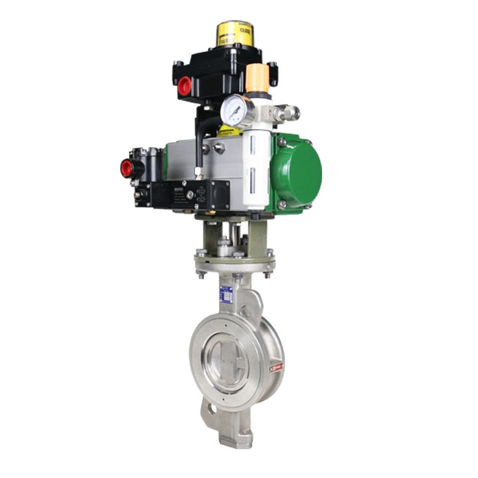
     Запорные вентили типа «бабочка» — незаменимые компоненты для регулирования потока с поворотом на четверть оборота, широко используемые в муниципальных и промышленных трубопроводных системах. Для правильного выбора, эксплуатации и обслуживания запорных вентилей типа «бабочка» крайне важно полностью понимать их принцип работы. принципы работыВ отличие от шаровых клапанов, работающих за счет вращения сферического шара, или задвижек с вертикальными подъемными конструкциями, в поворотных затворах используется уникальный дисковый механизм вращения. В данной статье систематически объясняются основные принципы работы, конструктивная логика, принцип герметизации, принцип дросселирования и различия в работе различных типов поворотных затворов, что обеспечивает профессиональную техническую поддержку при проектировании промышленных трубопроводов и применении клапанов. 1. Основной принцип работы дисковых затворовОсновной принцип работы поворотного затвора основан на Вращательное движение на четверть оборота на 90 градусов Внутренний диск. Шток клапана приводит диск во вращение в горизонтальном направлении в диапазоне от 0° до 90°, обеспечивая переключение и регулировку потока жидкости в трубопроводе. Весь рабочий процесс прост, эффективен и быстр, без сложной механической трансмиссионной конструкции. Полностью открытое состояние (90°)Когда диск вращается параллельно направлению потока жидкости, канал полностью открывается. Жидкость проходит через корпус клапана с минимальным сопротивлением потоку, обеспечивая высокую эффективность транспортировки по трубопроводу.Полностью закрытое состояние (0°)Когда диск вращается перпендикулярно направлению потока жидкости, его поверхность плотно прилегает к седлу клапана. Канал потока полностью перекрывается, обеспечивая надежную изоляцию трубопровода и перекрытие потока жидкости.Степень регулирования дроссельной заслонки (1°–89°)Диск может оставаться под любым промежуточным углом. Изменяя площадь перекрытия между диском и каналом потока, клапан точно контролирует расход жидкости, скорость среды и давление в трубопроводе, обеспечивая стабильное регулирование дросселирования. 2. Принцип работы конструкции: как основные компоненты взаимодействуют синергетически.Стабильная работа дисковых затворов обеспечивается скоординированной работой множества ключевых компонентов. Каждая деталь имеет независимый принцип действия и образует целостную систему управления потоком жидкости:Принцип передачи давления через шток клапанаВ качестве сердечника передачи крутящего момента шток клапана соединяет привод и диск. Он преобразует вращательный момент, создаваемый вручную, пневматически или электрически, в мощность вращения диска, обеспечивая синхронное и точное переключение углов.Принцип управления потоком дискаОбтекаемый диск является исполнительным компонентом для управления потоком жидкости. Угол его вращения напрямую изменяет поперечное сечение потока, обеспечивая линейную регулировку расхода и давления в трубопроводе.Принцип позиционирования корпуса клапанаКорпус клапана обеспечивает надежную опору при установке и защиту от давления. Он фиксирует положение штока и седла, обеспечивая точную посадку диска во время закрытия и предотвращая отклонения положения, влияющие на герметичность.3. Принцип работы герметизирующего механизма дисковых затворов.Качество уплотнения определяет надежность перекрытия поворотных затворов. В зависимости от конструкции уплотнения принципы работы делятся на мягкое и жесткое металлическое уплотнение, адаптированные к различным условиям эксплуатации в промышленности: 3.1 Принцип герметизации мягким швомВ поворотных затворах с мягким уплотнением в качестве уплотнительных элементов используются эластичные материалы, такие как EPDM, NBR и Viton. Когда затвор закрыт, диск сжимает эластичное седло, вызывая микродеформацию и заполняя крошечный зазор между диском и седлом. Этот принцип уплотнения за счет эластичного сжатия позволяетгерметичный, без протечекПодходит для работы с чистыми средами при нормальной температуре и низком давлении, такими как вода и воздух.3.2 Принцип герметизации металлическим жестким уплотнениемВ дисковых затворах с металлическим седлом используются металлические уплотнительные пары с износостойким покрытием из сплава. Благодаря точной механической обработке и высокоточной притирке металлический диск и металлическое седло обеспечивают жесткую и плотную посадку. Этот принцип механического сжатия не подвержен влиянию высоких температур и коррозии в средах, обеспечивая стабильную герметизацию в условиях высоких температур, высокого давления и абразивной обработки.4. Различия в принципах работы: концентрические и смещенные поворотные затворы.Концентрические и смещенные поворотные затворы имеют существенные различия в логике работы, что напрямую влияет на срок службы и устойчивость к давлению:4.1 Принцип работы концентрического поворотного затвораЦентр штока, центр диска и центр трубопровода полностью совпадают. Во время вращения диск непрерывно трется о поверхность седла. Конструкция проста и экономична, подходит для обычных условий работы при низком давлении и нормальной температуре с низкой частотой переключений.4.2 Принцип работы двух- и трехсмещенных поворотных затворов типа «бабочка»Благодаря уникальной смещенной конструкции диск автоматически отделяется от поверхности сиденья на начальном этапе вращения и соприкасается с сиденьем только в момент окончательного закрытия. принцип вращения без трения Устраняет износ седла, значительно повышает устойчивость к давлению и высоким температурам, а также подходит для тяжелых промышленных условий эксплуатации с частыми переключениями.5. Принцип работы привода автоматических поворотных затворовРазличные режимы работы обеспечивают разнообразную логику управления для поворотных затворов, удовлетворяя потребности в ручном и автоматическом промышленном управлении:Принцип ручного управления: Приводит в движение шестерню или шток через рычаг или маховик, создавая искусственный крутящий момент для управления вращением диска; применимо для низкочастотной работы на объекте.Принцип работы пневматической системы: Используется сжатый воздух для перемещения поршня привода, преобразуя энергию давления воздуха во вращательную механическую энергию, обеспечивая быстрое переключение клапана с превосходными взрывозащитными характеристиками.Принцип работы электроприводаЭлектродвигатель обеспечивает точное управление крутящим моментом и углом поворота, поддерживает дистанционную передачу сигналов и пропорциональную регулировку, реализуя интеллектуальное автоматическое управление трубопроводом.6. Рабочие характеристики и промышленное применение.Задвижки-бабочки, работающие на основе уникального принципа вращения на четверть оборота, отличаются быстрым откликом, малым сопротивлением потоку, компактной конструкцией и широкой адаптивностью к различным условиям эксплуатации. Они не только соответствуют традиционным требованиям к изоляции трубопроводов, но и обеспечивают точное регулирование потока, недоступное для традиционных задвижек. Благодаря надежной работе, они широко используются в водоочистке, системах отопления, вентиляции и кондиционирования воздуха, противопожарной защите, химической, энергетической и природоохранной отраслях промышленности.7. Технология высокоэффективных дисковых затворов GEKO ValveКомпания GEKO Valve тщательно оптимизирует конструкцию и рабочий механизм всех своих поворотных затворов. В наших концентрических и тройных поворотных затворах используются технологии прецизионного литья и зеркальной притирки, что обеспечивает гибкое вращение, точное управление углом и стабильную герметичность. Разнообразные конфигурации привода и уплотнения полностью соответствуют различным принципам работы в промышленности и требованиям применения, обеспечивая долгосрочные и стабильные решения для регулирования потока жидкости в глобальных промышленных трубопроводных системах.9 основных SEO-ключевых словПринцип работы промышленного поворотного затвора, высокопроизводительный поворотный затвор, поворотный затвор со смещением, поворотный затвор с нулевой утечкой, промышленный поворотный затвор на четверть оборота, механизм уплотнения поворотного затвора, поворотный затвор для тяжелых условий эксплуатации, автоматизированный поворотный затвор, поворотный затвор с регулированием потока.
    ЧИТАТЬ ДАЛЕЕ
1 2 3 4 5 6 7 8 9 10 11 12
Всего 12страницы

оставить сообщение

оставить сообщение
Если вас заинтересовала наша продукция и вы хотите узнать более подробную информацию, пожалуйста, оставьте сообщение здесь, мы ответим вам как можно скорее.
представлять на рассмотрение

Дом

Продукты

контакт